
Below is a list of some of the information you will be asked to provide during the data entry for a broadcasting certificate. This list is not exhaustive and is provided as a guide.
If you have any questions about this guide, email Innovation, Science and Economic Development Canada (ISED) at broadcasting-radiodiffusion@ised-isde.gc.ca.
Note: We recommend that you save your work often to avoid any loss of information.
On this page:
Acronyms and abbreviations
The following acronyms and abbreviations are used in this guide.
| AGL: | above ground level |
| AMSL: | above mean sea level |
| ATSC-M/H: | Advanced Television Systems Committee - Mobile/Handheld |
| CRTC: | Canadian Radio-television and Telecommunications Commission |
| dB: | decibels |
| dBc: | decibels relative to unmodulated carrier |
| dBd: | decibels relative to a dipole antenna |
| DTV: | digital television |
| EHAAT: | effective height above average terrain |
| ERP: | effective radiated power |
| EU value: | usable field strength |
| HAAT: | height above average terrain |
| HRAG: | height of the roof above ground |
| HVIN: | hardware version identification number |
| IBOC: | in-band on-channel |
| m: | metre(s) |
| mV: | millivolt(s) |
| Q factor: | quality factor |
| RBDS: | Radio Broadcast Data System |
| RC: | radiating centre |
| RMS: | root mean square |
| SCMO: | subsidiary communication multiplex operations |
| TX: | transmit (or transmitter) |
| W: | watt(s) |
| WGS84: | World Geodetic System 1984 |
Broadcasting certificates
Use the information below as a guide when you are applying for a new broadcasting certificate or making modifications to an existing broadcasting certificate.
NOTE: Before entering information for an IBOC, AM or DTV station, refer to their respective additional information sections below for instructions specific to these stations.
General Information
- Is it an Experimental Authority? – Default is "No" (enter "No" for IBOC)
- Requested Duration (required):
- Standard Term - Applies to most situations
- Short Term – Normally used for special events (maximum of 28 days)
- Temporary Operation – Used when temporary measures are needed to continue broadcasting during unforeseen circumstances (maximum of 365 days, could be extended in some situations if sufficiently justified)
- Start and End Dates – Appears when "Short Term" or "Temporary Operation" are selected to specify the start and end dates of that period
- Client Reference (optional) – Can be used to store your own reference number
Click NEXT to continue.
Account Information
- Click the Account Information’s EDIT button if you want to update any of the following:
- Account number – System generated number that identifies the licence holder
- Licensee – Legal name of the certificate holder
- Administrative contact - Who should be contacted for general information about the certificate
- Technical contact – Who should be contacted for technical information about the certificate
Usage/Other Information
- Purpose of the application (required)
- Change of facilities
- Change of address
- Transfer of assets
- Addition of auxiliary or IBOC transmitter
- Change of call letters
- New
- Other
- Addition of multiplexed operation (DTV only)
Note: Use choices (ii) to (v) only if one of those choices is the reason for the modification; otherwise use (i).
If you select "Other" for the purpose, add a short description - Any other supporting information – Additional details about the proposal or change being requested
Click NEXT to continue.
List of Stations
- Click EDIT to enter information about the main station
- When entry is complete, you will be returned to this page to enter information on other stations, such as an auxiliary station (see Auxiliary Station below for instructions)
- For new applications, the fields will be blank.
- For modifications, some of the fields will be pre-populated with information from the certificate in our database (location, call sign, coordinates, ERP, etc.)
Main Station – General Details
- Requested Frequency (MHz) (required)
- Channel Number (required)
- For FM, Click Calculate From Frequency to populate the channel number
- For DTV, click Calculate from channel to populate the frequency
- For AM, enter the same value for both frequency and channel
- Rebroadcasting Station (required) - Yes/No (if the technical brief provides the originating station, chose "Yes" and click LOOKUP to select the station)
- Originating Station – required if "Yes" was chosen at Rebroadcasting Station (click LOOKUP to select the station)
- Broadcast Mode (required) - Stereo or Mono (not applicable to DTV)
- Are you adding a SCMO Ancillary Service to this application? – Yes/No (applies to FM only)
- Note that RDBS is a type of SCMO
- Program Feed – Select the appropriate feed from studio to transmitter site
- If you chose "Other" at Program Feed, enter a description
Click NEXT to continue.
Main Station – SCMO Ancillary Service (Applies to FM only)
For an SCMO, ensure that entries follow the format described below.
The technical brief should clearly indicate if SCMO or RBDS (most common type of SCMO) is going to be used. Do not remove existing SCMO when entering a modification; however, make sure that the correct format is being used.
- SCMO 1 – Enter the information as per this format: "## kHz – Description"
- The "Description" must be one of the following:
- RBDS
- Non broadcast services
- Broadcasting
- Services related to station
Example: 57 kHz – RBDS
- The "Description" must be one of the following:
- SCMO 2
- SCMO ...
Main Station – Proposed Parameters (auxiliary station will start at Site Information section)
- CRTC Licence Exempt - Yes/No
- CRTC Exemption Order Number (required) – If "Yes" was selected at CRTC Licence Exempt, enter the CRTC Exemption Order Number. For modifications, the previous CRTC decision number may be listed at the Exemption Order Number only if "No" was selected. These fields must be empty if a CRTC licence is required.
- Principal Service Area (required)
- Province (required) - For the principal service area
- Station Class (required)
- Call Sign (required) – For a new application, if no specific call sign is being requested, choose one from the List of Available Call Signs For Broadcast Stations; if a specific call sign is being requested, ensure that is it valid and not already in use
Site Information
Enter information where the transmission site is located
- Street Address or Site Name (required)
- City
- Province or Territory (required)
Geographical coordinates (WGS84)
- Latitude (required)
- Longitude (required)
Note: Latitude and Longitude may be referred to as "Antenna Coordinates" or "Site Coordinates" in the brief.
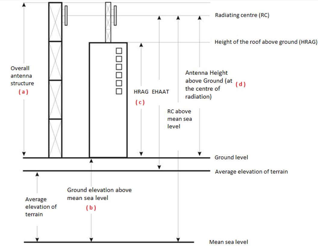
- Overall antenna structure height above ground level [m] (required) – (a) overall height
- Ground elevation above mean sea level (AMSL) [m] (required) – (b) ground level
- Height of the roof above ground (HRAG) [m] (required) – (c) rooftop height (leave blank if not on top of a building)
- Antenna height above ground level (AGL) (at the centre of radiation) [m] (required) – (d) radiating centre (RC) height
Refer to the figure below for representations of (a), (b), (c) and (d)
Description of figure
This figure is an example of an elevation diagram of typical tower and transmitting antenna structures.
- The tower is drawn as a vertical pole and the antenna is shown as a small vertical structure attached to the tower.
- The ground level is drawn as a horizontal line running at the base of the tower.
- There is a bidirectional arrow between the top of the tower and the line at ground level, indicating the overall antenna structure height above ground level, indicated with the letter (a).
- The line representing the average elevation of terrain is drawn as a horizontal line slightly below ground level.
- Mean sea level is shown as a horizontal line at the bottom of the graphic, below the average elevation of terrain.
- A bidirectional arrow between the line at ground level and the line at mean sea level indicates the ground level elevation above mean sea level (AMSL), indicated with the letter (b).
- There is a bidirectional arrow between the roof of the building and the line at ground level indicating the height of the roof above ground (HRAG), indicated by the letter (c).
- A horizontal line runs from the vertical centre of the antenna and is identified as the radiating centre (RC).
- There is a bidirectional arrow between the radiating centre of the antenna and the line at ground level, indicating the antenna height above ground level (AGL) at the centre of radiation, indicated by the letter (d).
- There is a bidirectional arrow between the radiating centre of the antenna and the line of the average elevation of terrain, which indicates the effective height above average terrain (EHAAT).
- There is a bidirectional arrow between the line marking the radiating centre of the antenna and the line at mean sea level, indicating the height of the radiating centre above mean sea level.
Radiocommunication and Broadcasting Antenna Systems Attestation
- Provide Site Attestation as an Attachment (required):
- Select "Yes" to upload your completed ISED-ISDE2430: Radiocommunication and Broadcasting Antenna Systems Attestation form by selecting the file then click Add Attachment (important for file to be attached)
- Select "No" to complete this information online, which will appear on next page
- For a modification, select "N/A" if there are no changes being made to the current antenna system
- Letter of Intent (Main Station only)
Note: The Letter of Intent is a letter to the land-use authority or municipal government responsible for the proposed site location informing them of the proposal. It is required when you want to perform the land-use authority consultation after a CRTC decision is issued. Consult CPC-2-0-03 - Radiocommunication and Broadcasting Antenna Systems for more information.
Click NEXT to continue.
Radiocommunication and Broadcasting Antenna Systems Attestation (online option)
-
If on the previous page you selected "No" to providing the Radiocommunication and Broadcasting Antenna Systems Attestation form as an attachment, this section contains an online version of the form. Consult CPC-2-0-03 for more information on how to fill out this section.
After you fill out the form, click NEXT to continue.
Main or Auxiliary Station – Transmitter Specifications
Transmitter Specifications
- Click LOOKUP to search for the manufacturer name and model/type number, then select the appropriate one from the search results and click OK
-
If the technical brief doesn’t specify information about the transmitter, click the checkbox Details about equipment will be specified at the on-air certification stage and the applicant will ensure that the transmitter will be type-approved
Transmitter Specifications Search
- Hardware Version Identification Number (HVIN) – Enter the model/type of the transmitter
- Company Name – Enter the manufacturer of the transmitter
- Click SEARCH to display the search results
- If the transmitter is not found, sometimes inputting part of the model number before or after a dash/space may yield more results
Transmitter Configurations
- Transmitter Output Power (W) – Found in the brief; enter the Operating Power not the Rated Output Power
Click NEXT to continue.
Main or Auxiliary Station – Transmission Line
For a modification not related to selected station you can enter "1" under each field below, followed by the CALCULATE action to indicate no changes and pass validation.
- Manufacturer (required)
- Type (required)
- Length [m] (required)
- Line Loss [dB/100m] (required)
- Efficiency [%] (required) - Click CALCULATE to populate the field
- Other Losses – Enter if specified in the brief; otherwise leave blank
Main or Auxiliary Station – Antenna Data
Antenna Specifications
- Manufacturer (required)
- Model (required)
- Number of Antenna Bays (required)
- Total Vertical Dimension of All Antenna Elements [m] (required)
Additional Attributes
- Polarization (required)
- Radiation Pattern (required)
- Maximum Antenna Gain [dBd] (required)
- Average Antenna Gain (Horizontal) [dBd] (required)
- Maximum Antenna Gain (Vertical) [dBd] (required)
- Average Antenna Gain (Vertical) [dBd] (required)
Click Set Gain Values to enter data (do not use this step for a modification if the antenna parameters remain the same as before, or the previous gains will be cleared).
Set Antenna Details – Step 1
- Polarization (required)
- Radiation Pattern (required)
Select the Antenna Polarization and Radiation Pattern.
Click NEXT to continue.
Set Antenna Details – Step 2
- Maximum Antenna Gain (Horizontal) [dBd] (required)
- Average Antenna Gain (Horizontal) [dBd] (required)
- Maximum Antenna Gain (Vertical) [dBd] (required)
- Average Antenna Gain (Vertical) [dBd] (required)
Precision of gains above is up to 3 decimal values. The list will vary depending on the values selected in step 1.
Click APPLY after entering all necessary gains.
Antenna Configuration
- Beam Tilt [deg] (required) – Positive indicates down tilt; enter "0" if there is no tilt
- Attach PAT File (required for new or if antenna will be different for a modification) – Click Select File to include a file then Add Attachment
Click NEXT to continue.
Main or Auxiliary Station – Effective Radiated Power (ERP) Calculations | HAAT Values
- EHAAT – Effective height above average terrain
- ERP Max (H) – Enter "0" if vertically polarized
- ERP Max (V) – Enter "0" if horizontally polarized
Click Set Power Values to calculate the remaining values.
Click NEXT to continue.
Main or Auxiliary Station – Attachments
- Click Select File to attach the engineering brief
- Repeat for every other related documents to the application
- Remember to click Add Attachment after each one to upload the file
Click NEXT to continue
Main Station – Summary
- At the Main Station – Summary page, you can verify and edit previously entered information by clicking one of the EDIT buttons.
When done, click NEXT to return to the List of Stations page.
Auxiliary Station – Proposed Parameters
- Click Add Aux Stations to enter information on your auxiliary station(s). Refer to previous instructions for guidance. If you have no auxiliary station, click Save then NEXT to continue.
- Station type: select Alternate or Standby transmitter
- For an alternate transmitter, the Output Power, Coordinates, and Antenna Height should be the same as the main transmitter
- If the auxiliary transmitter information is exactly the same as that of the main station, click Load data from Main Station
- Attachments were added with the Main Station, this step can be skipped
- Service Mode: Leave to "Please select…" when adding an alternate or standby transmitter.
- Call Sign – The Call Sign will be indicated as "XXXX-FM-AX#"
Click NEXT to continue.
Review and Submission of the Application
- This is the final page of the application. Write down the Application Number shown in parentheses and refer to it in future communications with ISED.
- When the entry of information is completed and the application is ready for submission, click Save then Validate to confirm the application is complete.
- An error message will be displayed to the right of sections where validation failed. Click its corresponding EDIT button to make the required corrections. Save and Validate as required until all validations are passed successfully.
- Select Submit to ISED when your application has been successfully validated.
Additional information for IBOC transmitter (transmission of digital and analog signals simultaneously)
The information below is specific to the addition of an in-band on-channel (IBOC) transmitter to an existing or new FM station. Follow the same procedure as in Broadcasting certificates, above, noting the differences listed below.
Usage/Other Information
- At "Purpose of Application", select "Addition of auxiliary or IBOC transmitter" if this is the only change being proposed
List of Stations
- From this section, the main station and any auxiliary station(s) will be listed
- It is recommended to Validate the related analog station that the IBOC will be linked to, to reduce errors when data will be copied
- To add the IBOC transmitter, you will need to add an auxiliary station
- Click Add Auxiliary Station
Remaining Sections
For all remaining sections, use Load data from Main station if the IBOC is linked to the main transmitter; otherwise you will need to manually re-copy the fields of each section of the auxiliary transmitter that the IBOC is linked to:
- Auxiliary Station – Proposed Parameters
- Station Type – Select "IBOC Station"
- Service Mode – Select the mode as per the technical brief
- Call Sign – The Call Sign will be indicated as "XXXX-HD"
- Provide site attachment as an attachment:
- Can be set to "N/A" for IBOC if already provided
- For new, you will need to attach it again to pass validation (or a TXT file containing at least one character in the content)
- Auxiliary Station - Transmitter Specifications
- Auxiliary Station - Transmission Line
- Auxiliary Station - Antenna Data
- Attach PAT File can be left empty for a modification; however, for a new application it will be required to pass validation (attach same PAT file as analog station it is linked to)
- Auxiliary Station - Effective Radiated Power Calculations (ERP) | HAAT Values
- Lower Sideband [dBc] (required) – Enter information from the brief without a negative sign
- Upper Sideband [dBc] (required) – Enter information from the brief without a negative sign
Remember to attach the documentation and engineering brief as explained above if not already done.
Additional information for AM regular-power and low-power stations
Follow the same procedure as in Broadcasting certificates, above, noting the differences listed below.
Main Station – General Details
- Any critical hours parameters (required) – Select the appropriate value for the station
- Attended:
- Non-attended (default) - Use this option if the transmission site will be remotely controlled and monitored
- Attended – Use this option if the transmission site will be locally controlled and monitored
Main Station – Proposed Parameters
- Station Class – Specified in the technical brief. If the proposal is using the extended band (frequency between 1605 kHz and 1705 kHz), leave Station Class as "Please select…"
- Do you have separate sites for Day and Night operations? – As it is possible for AM stations to operate from different sites for day and night operations, select "Yes" or "No" as applicable.
- If "Yes", the following information is required:
Site Details for Day
- Enter information as per the brief
- Enter information as per the brief
Main Station – AM Radio General Details
- Power (Radiated) Day [W] (required) – Enter as per the brief
- Power (Radiated) Night [W] (required) – Enter as per the brief
- Transmitter Output Power [W] (required) – Enter as per the brief
- RMS Day [mV/m] (required) – Enter as per the brief
- RMS Night [mV/m] (required) – Enter as per the brief
- Q factor – Day [mV/m] (required) – Enter as per the brief; if none, enter "0"
- Q factor – Night [mV/m] (required) – Enter as per the brief; if none, enter "0"
- EU Value (Night Interval Only) [mV/m] (required) – Enter as per the brief
Additional information for DTV regular-power and low-power stations
Follow the same procedures as in Broadcasting Certificates, above, noting the differences listed below.
Main Station – General Details
- At the question Will the station use multiplexing to transmit additional broadcasting program services? select "Yes" if this will be the case, "No" otherwise
Main Station – List of Additional Multiplexed Broadcasting Programs
- Click Add Program to add a new multiplex entry
- Call Sign (required)
- Account Number (if known)
- Company Name (required)
- Additional Information
- Use the LOOKUP button to populate the above fields if required
Main Station – Transmitter Specifications
New Transmitter Details
- Does this support ATSC-M/H? – Select "Yes" if proposed transmitter supports the mobile/handheld extension for DTV
- Manufacturer – Enter if known during application; otherwise leave blank
- Model Number – Enter if known; otherwise leave blank
- Rated TX Power [W] – Enter if known; otherwise leave blank