
August 2021
Note: The closing of the technical consultation has been extended to Monday, August 23, 2021.
1. Intent
Through the release of this document, Innovation, Science and Economic Development Canada (ISED), on behalf of the Minister of Innovation, Science and Industry (the Minister), is hereby initiating a 15-day technical consultation, closing on August 21, 2021, on proposed amendments to Standard Radio System Plan SRSP-520, Technical Requirements for Fixed and/or Mobile Systems, Including Flexible Use Broadband Systems, in the Band 3450-3650 MHz (the SRSP).
2. Background
In March 2020, ISED published the Policy and Licensing Framework for Spectrum in the 3500 MHz Band, which included the conditions of licence for flexible-use spectrum licences in the 3450-3650 MHz band (the 3500 MHz band). The SRSP, which can be amended from time to time, must be followed by all licensees in the 3500 MHz band as part of their conditions of licence and applies to all existing and new fixed and mobile stations. This consultation seeks comments on proposed revisions to the SRSP to include measures to protect radio altimeters operating in the frequency band 4200-4400 MHz from harmful interference.
Radio altimeters are sensors installed on most civil and military aircraft and operate in the 4200-4400 MHz band. They continuously measure an aircraft's altitude above ground level in flight and provide direct measurement of its clearance over terrain and obstacles. They also feed information to other systems on board the aircraft, including the automated landing and collision avoidance systems.
Spectrum regulators around the world, including ISED, have recently become aware of studies that have shown a possibility of interference to radio altimeters from signals outside their band of operation, which could include signals from future flexible use 5G systems in 3500 MHz spectrum around airports.
Accordingly, on March 26, 2021, ISED published Spectrum Advisory Bulletin SAB-001-21, Radio Altimeters and Technical Rules in the 3450-3650 MHz Band (3500 MHz Band), which provided notice that ISED would continue to monitor and study this issue as it develops and, if necessary, update technical rules in the 3500 MHz band to mitigate potential interference to radio altimeters. Spectrum regulators continue to examine the issue of radio altimeter interference, and rules limiting 5G operation in the bands below 4200 MHz have been implemented in Japan and France.
3. Proposed changes
There is preliminary evidence that radio altimeter devices, which are used to aid in aeronautical navigation, may be affected by operations in the 3500 MHz band. The proposed changes to the SRSP (in particular section 10 and annexes D and E of the annex to this consultation) would modify outdoor antenna tilt requirements in all areas and limit outdoor operations in areas immediately surrounding specific airports, in order to help ensure that radio altimeter devices operating in the 4200-4400 MHz band are not affected by 3500 MHz operations. The proposed changes will come into effect immediately upon publication of the SRSP following this consultation period. The proposed changes to SRSP-520 do not apply to fixed systems already in operation that are compliant with SRSP-303.4, Technical Requirements for Fixed Wireless Access Systems Operating in the Band 3475-3650 MHz.
New standards for radio altimeters are expected to be available in the future to address these interference concerns. However, it could take several years to implement, certify and deploy new equipment on existing aircraft. Moreover, additional studies are underway in Canada and in other countries to further assess the potential adjacent band interference to radio altimeters from flexible use. ISED anticipates that additional evidence will be available throughout the balance of this year and into 2022. Further changes may be proposed to the SRSP at that time, following further consultation.
4. Next steps
ISED will review the comments received and publish an updated SRSP after the closing of the technical consultation.
5. Submitting comments
Respondents are requested to provide their comments in electronic format (Microsoft Word or Adobe PDF) by email.
Paper submissions should be mailed to the following address:
Innovation, Science and Economic Development Canada
Senior Director, Terrestrial Engineering and Standards
235 Queen Street (6th Floor, East Tower)
Ottawa ON K1A 0H5
6. Obtaining copies
All spectrum-related documents referred to in this paper are available on ISED's Spectrum Management and Telecommunications website.
Annex: Draft Standard Radio System Plan SRSP-520, Technical Requirements for Fixed and/or Mobile Systems, Including Flexible Use Broadband Systems, in the Band 3450-3650 MHz, issue 2
Preface
Standard Radio System Plan SRSP-520, issue 1, Technical Requirements for Fixed and/or Mobile Systems, Including Flexible Use Broadband Systems, in the Band 3450-3650 MHz, dated July 2020 replaced SRSP-303.4, Technical Requirements for Fixed Wireless Access Systems Operating in the Band 3475-3650 MHz, issue 3. SRSP-520 sets out the minimum technical requirements for the efficient use of the band 3450-3650 MHz and applies to all fixed and mobile systems, including flexible use broadband systems, operating in the band. However, as indicated in section 5 of SRSP-520, specific provisions of SRSP-303.4, issue 3, continue to apply for fixed spectrum licences issued prior to June 2019, and for fixed spectrum licences issued after June 2019 as a result of the conversion of existing fixed spectrum licences from Tier 4 to Tier 5 licence areas.
SRSP-520, issue 2, imposes measures to address the protection of radio altimeters operating in the frequency band 4200-4400 MHz from harmful interference.
Issued under the authority of
the Minister of Innovation, Science and Industry
Martin Proulx
Director General
Engineering, Planning and Standards Branch
1. Intent
1. This Standard Radio System Plan (SRSP-520) replaces SRSP-303.4, Technical Requirements for Fixed Wireless Access Systems Operating in the Band 3475-3650 MHz, issue 3. SRSP-520 sets out the minimum technical requirements for the efficient use of the band 3450-3650 MHz (3500 MHz band) and applies to all fixed and mobile systems, including flexible use broadband systems, operating in the band. (“Flexible use” refers to deployment of mobile and/or fixed services.) However, as indicated in section 5 of SRSP-520, specific provisions of SRSP-303.4, issue 3, continue to apply for fixed spectrum licences issued prior to June 2019, and for fixed spectrum licences issued after June 2019 as a result of the conversion of existing fixed spectrum licences from Tier 4 to Tier 5 licence areas.
2. This SRSP is intended to aid in the design of radio systems and specifies the technical characteristics relating only to efficient spectrum usage; it is not to be regarded as a comprehensive specification for equipment design and/or selection.
2. General
3. This SRSP is based on current and planned technologies being considered by service provider(s) for implementing flexible use broadband systems in Canada. Revisions to this SRSP will be made as required.
4. Notwithstanding the fact that a system satisfies the requirements of this SRSP, Innovation, Science and Economic Development Canada (ISED) may require adjustments to radio and auxiliary equipment in radio stations whenever harmful interference is caused to other radio stations or systems. “Harmful interference,” as defined in the Radiocommunication Act, means an adverse effect of electromagnetic energy from any emission, radiation or induction that (a) endangers the use or functioning of a safety-related radiocommunication system; or (b) significantly degrades or obstructs, or repeatedly interrupts, the use or functioning of radio apparatus or radio-sensitive equipment.
5. The arrangements for non-standard systems are outlined in Spectrum Utilization Policy SP Gen, General Information Related to Spectrum Utilization and Radio Systems Policies.
6. ISED should be advised when potential conflict between radio systems cannot be resolved by the parties concerned. After consultation with these parties, ISED will determine what modifications need to be made and establish a schedule for these modifications in order to resolve the conflict.
7. ISED may require licensees to use receiver selectivity characteristics that provide improved rejection of harmful interference.
8. Equipment operating under flexible use licences in the 3450-3650 MHz band must be certified in accordance with the latest issue of Radio Standards Specification RSS-192, Flexible Use Broadband Equipment Operating in the Band 3450-3650 MHz. Equipment operating under fixed use spectrum licences may continue to operate, provided that such equipment has been previously certified in accordance with RSS-192, issue 3. Furthermore, operation under fixed use spectrum licences is subject to the operational conditions defined in section 5 of this SRSP.
9. Licensees are required to make information on certain technical parameters of their radio systems available to ISED upon request.
3. Related documents
10. The current issues of the following documents are applicable and are available on the Spectrum management and telecommunications website.
Interim Statement of Intent Between the Federal Communications Commission of the United States of America and the Department of Innovation, Science and Economic Development Canada Related to the Sharing and Use of the Frequency Band 3550-3650 MHz by Fixed and Mobile Services Along the Canada-United States Border (forthcoming)
CTFA – Canadian Table of Frequency Allocations
DGSO – Canada Gazette Notice
RSP – Radio Standards Procedures
RSS – Radio Standards Specifications
SAB – Spectrum Advisory Bulletin
SLPB – Canada Gazette Notice
SP – Spectrum Utilization Policies
TRAA – Terrestrial Radiocom Agreements and Arrangements
4. Definitions
11. The following terms are used in this document.
- Active antenna system (AAS)
- An antenna system where the amplitude and/or phase between antenna elements is dynamically adjusted resulting in an antenna pattern that varies in response to short-term changes in the radio environment. AAS may be integrated in a point-to-multipoint (P-MP) hub station, base station and non-fixed subscriber equipment. Antenna systems used for long-term beam shaping such as fixed electrical down tilt are not considered an AAS.
- AAS base station equipment
- A base station with an AAS antenna system.
- Non-active antenna system (Non-AAS)
- An antenna system that does not meet the definition of AAS.
- Non-AAS base station equipment
- A base station with a non-AAS antenna system.
- Adjacent frequency block group
- In the context of this SRSP, adjacent frequency block group is defined as a continuous frequency range of multiple block(s) of 10 MHz that contains the equipment’s channel bandwidth. For equipment with channel bandwidth smaller than 10 MHz, the frequency block group is the frequency range of a 10 MHz block.
- Antenna height above average terrain (HAAT)
- The height of the centre of radiation of the antenna above the average elevation of the terrain between 3 and 16 km from the antenna, for an individual radial. The final antenna HAAT (also known as the effective height of the antenna above average terrain (EHAAT)) is the average of the antenna HAATs for 8 radials spaced every 45 degrees of azimuth starting with true north.
5. Fixed use spectrum licences issued prior to June 2019
12. Fixed stations operating under fixed spectrum licences issued prior to June 2019 may continue to operate under SRSP-303.4, issue 3. Continued operation under SRSP-303.4, issue 3, also applies to Tier 5 area fixed spectrum licences issued after June 2019 as a result of the conversion of existing Tier 4 area fixed spectrum licences issued prior to June 2019 to Tier 5 areas. Modifications to existing fixed stations are allowed as long as the modifications comply with SRSP-303.4, issue 3. Any modified station not in compliance with SRSP-303.4, issue 3, will be considered a new fixed station. New fixed stations are permitted, provided that they comply with all requirements specified in SRSP-520 with the exception of paragraphs 16 and 17, where they shall comply with the band plan specified in SRSP-303.4, issue 3. Collectively, stations deployed under these fixed spectrum licences are hereafter referred to as “fixed spectrum licence deployments.”
13. Notwithstanding compliance with SRSP-303.4, issue 3, or SRSP-520, all fixed spectrum licence deployments are subject to the transition plan outlined in section 6.9 of SLPB-001-19, Decision on Revisions to the 3500 MHz Band to Accommodate Flexible Use and Preliminary Decisions on Changes to the 3800 MHz Band, the transition process general guidelines outlined in section 15 of SLPB-001-20, Policy and Licensing Framework for Spectrum in the 3500 MHz Band,and the 3500 MHz Transition Manual.
14. The guidelines for coordination to resolve possible interference conflicts between fixed spectrum licence deployments and stations operating under flexible use licences are outlined in the 3500 MHz Transition Manual.
15. The guidelines for coordination to resolve possible interference conflicts between fixed spectrum licence deployments are outlined in SRSP-303.4, issue 3.
6. Band plan
16. The block structure for flexible use broadband systems in the 3500 MHz band is shown in figure 1.
Figure 1: 3500 MHz band plan
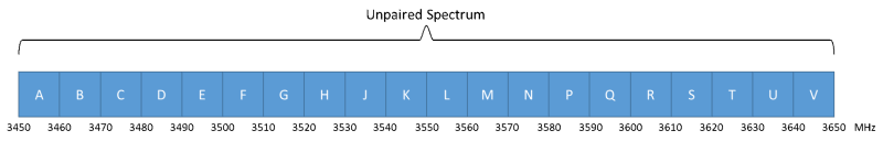
Description of figure 1
This figure shows the 3500 MHz band plan, which includes the frequency range of 3450 to 3650 MHz. The frequency range is divided into 20 unpaired blocks of 10 MHz each.
17. Frequency blocks available for licensing in the the 3450-3650 MHz band are intended for use with time division duplexing (TDD) systems. The band is divided in 20 unpaired blocks of 10 MHz. Frequency blocks can be aggregated to form a frequency block group. A frequency block group is a continuous frequency range of multiple block(s) of 10 MHz.
18. Non-TDD flexible use broadband systems operating in the 3450-3650 MHz band may be deployed. Such systems shall not interfere with, nor claim protection from, TDD flexible use broadband systems. Furthermore, flexible use broadband system licensees using non-TDD technology are required to provide sufficient guard bands or other mitigation measures such as the use of external filters, to reduce equivalent isotropically radiated power (e.i.r.p.) or total radiated power (TRP) to levels that are consistent with the unwanted emission limits set out in RSS-192.
19. Operations of new flexible use broadband systems according to the above band plan are subject to the timelines of the transition plan outlined in SLPB-001-19, the transition process general guidelines SLPB-001-20, and the 3500 MHz Transition Manual.
7. Technical criteria
20. This section covers technical criteria in regards to power, antenna height and use of multiple-input-multiple-output (MIMO) antennas.
7.1 Fixed and base stations using non-active antenna systems
21. This section outlines the technical criteria for fixed and base stations using non-active antenna systems (non-AAS).
7.1.1 E.i.r.p. for non-AAS correlated transmission
22. When multiple non-AAS antennas are used at a station to transmit the same digital data in a given symbol period (even with different coding or phase shifts) for transmit diversity, or to steer signal energy towards a particular direction for enhanced directional gain (i.e. beamforming), or to devise any other transmission mode where signals from different antennas are correlated, the equivalent isotropically radiated power (e.i.r.p.) shall be calculated based on the aggregate power conducted across all antennas and resulting directional gain 10log10(N)+GmaxdBi. Here, N is the number of antennas and Gmax is the highest gain in dBi among all antennas.
7.1.2 E.i.r.p. for non-AAS uncorrelated transmission
23. When multiple non-AAS antennas are used at a station in which each antenna transmits different digital data during any given symbol period (i.e. space-time block codes) or independent parallel data stream over the same frequency bandwidth in order to increase data rates (i.e. spatial multiplexing), or from any other transmission mode where signals from different antennas are completely uncorrelated, the e.i.r.p. shall be calculated based on the aggregate power conducted across all antennas and maximum antenna gain Gmax.
7.1.3 E.i.r.p. limits and antenna height limits
24. For fixed point-to-point (P-P) stations and flexible use base stations transmitting in accordance with section 6 of this SRSP within the frequency range 3450-3650 MHz with a channel bandwidth equal to or greater than 5 MHz, the maximum permissible e.i.r.p. is 68 dBm/5 MHz (i.e. no more than 68 dBm e.i.r.p. in any 5 MHz band segment) for stations with an antenna height above average terrain (HAAT) of up to 305 metres. For stations with a channel bandwidth less than 5 MHz, the maximum permissible e.i.r.p. is 61 dBm/MHz.
25. For all installations with an antenna HAAT of more than 305 metres, a corresponding reduction in e.i.r.p. according to the following formula shall be applied:
\[ e.i.r.p._{reduction} = 20log_{10} (HAAT / 305) dB \]
26. The HAAT of a fixed P-P station or flexible use base station with multiple antennas shall be calculated with reference to the highest antenna.
27. In mountainous areas where a licensee can demonstrate that the installation will not cause interference to other licensees in adjacent geographical service areas, this e.i.r.p. reduction is not required. In the context of this SRSP, a “mountainous area” is defined as a location, where the ground level of the site has a HAAT of 300 metres and there is a terrain feature within 50 km that rises to an elevation higher than the ground level of the site. However, if an interference case arises involving any stations with HAAT above 305 metres, then the station(s) with HAAT above 305 metres will be required to reduce e.i.r.p. according to the formula in paragraph 25, above.
7.2 Fixed and base stations using active antenna systems
28. This section outlines the technical criteria for fixed and base stations using active antenna systems (AAS).
7.2.1 Total radiated power for AAS transmission
29. Total radiated power (TRP) in watts is defined as the integral of the power transmitted by the AAS station in different directions over the entire radiation sphere.
\[ TRP \ {\underline{\underline{def}}} \ \frac{1}{4\pi} \ \int_{0}^{2\pi} \ \int_{0}^{\pi} \ P(\Theta,\varphi)sin(\Theta)d \Theta d\varphi \]
Where
P(θ,φ): power radiated in watts by an antenna array system in direction (θ,φ)
\[ P(\Theta,\varphi) = P_{Tx} g(\Theta,\varphi) \]
Where
PTX: conducted power (watts) input to the array system
g(θ,φ): array systems directional gain (referencing an isotropic radiator) along (θ,φ) direction
7.2.2 Total radiated power limits and antenna height limits
30. For flexible use base stations transmitting in accordance with section 6 of this SRSP within the frequency range 3450-3650 MHz with a channel bandwidth equal to or greater than 5 MHz, the maximum permissible TRP is 47 dBm/5 MHz (i.e. no more than 47 dBm TRP in any 5 MHz band segment). For stations with a channel bandwidth less than 5 MHz, the maximum permissible TRP is 40 dBm/MHz.
31. Antenna height limits shall apply based on equivalent e.i.r.p. of the AAS antenna system. The equivalent e.i.r.p. in dBm/5 MHz shall be calculated as follows.
\[ (e.i.r.p.)_{eq} = TRP + G_{e} + 10 log_{10}(min(N_{Tx},8)) \]
where Ge is the gain of one antenna element in dBi, NTX is the number of transmit antenna elements and TRP is measured in dBm/5 MHz. An equivalent e.i.r.p. of 68 dBm/5 MHz applies to an antenna installation with a HAAT of 305 metres or lower.
32. For any installation with a HAAT above 305 metres, TRP shall be reduced according to the following formula.
\[ TRP_{reduction} = 20log_{10} (HAAT / 305) dB \]
33. In mountainous areas where a licensee can demonstrate that the installation will not cause interference to other licensees in adjacent geographical service areas, this TRP reduction is not required. However, if an interference case arises involving any stations with HAAT above 305 metres, then the station(s) with HAAT above 305 metres will be required to reduce TRP according to the formula in paragraph 32, above.
7.3 Power limits for subscriber equipment
34. A wide array of subscriber equipment (e.g. mobile, nomadic, portable and fixed subscriber equipment) is expected to be supported by flexible use broadband systems. Maximum power limits for subscriber equipment are specified in RSS-192. The equipment should employ automatic transmit power control such that stations operate on the minimum required power.
7.4 Transmitter unwanted emissions
35. Transmitter unwanted emissions are specified in RSS-192.
8. General guidelines for the coexistence of flexible use broadband systems operating in the same frequency blocks and in adjacent service areas
36. This section deals only with coexistence between flexible use broadband systems. See section 5 of this SRSP for coordination guidelines for resolving possible interference conflicts between fixed spectrum licence deployments, or between fixed spectrum licence deployments and flexible use broadband systems.
37. When several flexible use licensees are authorized to operate systems using the same frequency block in adjacent licensing areas, coordination of any transmitter installations that are close to the licence area boundary shall be required to eliminate any harmful interference that might otherwise exist and ensure continuance of equal access to the frequency block by the affected licensees.
38. Fixed P-P stations or flexible use base stations must not generate a power flux density (pfd) outside the licensed service area that exceeds 114.5 dBW/m2 in any 1 MHz, unless agreed otherwise by the affected licensee. The pfd of 114.5 dBW/m2/MHz corresponds to approximate field strength of 31.3 dBuV/m/MHz and receiver power of 116.9 dBm/MHz. An example of a calculation for pfd is given in annex B.
39. A pfd of –114.5 dBW/m2/MHz may be exceeded at or beyond a flexible use licensee’s service area boundary on a provisional basis where, within 70 km of its service area boundary, there is no station deployment by the neighbouring licensee (70 km zone). Licensees are encouraged to consult ISED’s Spectrum Management System for the latest deployment data for stations within 70 km of their service area boundary, and shall notify the licensees operating in the adjacent area for which the pfd of 114.5 dBW/m2/MHz is exceeded. However, in the event that new stations are deployed by the neighbouring licensee within the 70 km zone, both licensees will be required to meet the pfd at their respective service area boundary, unless otherwise agreed by both licensees.
40. Any fixed P-P station or flexible use base station will require further coordination with relevant flexible use licensees where any proposed modifications:
- result in a pfd at or beyond the other service area boundary exceeding a pfd of 114.5 dBW/m2/MHz; or
- involve operation on frequencies not previously coordinated; or
- change the polarization.
41. Possible harmful interference conflicts resulting from the operation of two flexible use broadband systems in adjacent geographical service areas may occur. The resolution of those conflicts should be arrived at through mutual arrangements between the affected parties following consultation and coordination. When potential conflicts between systems cannot be resolved in a timely fashion, ISED shall be so advised, whereupon, following consultations with the parties concerned, ISED will determine the necessary course of action.
42. System expansion measures, such as addition of cells, cell splitting and sectorization, must not force major changes in the system of the flexible use licensee in the adjacent geographical service area, except by mutual agreement between the affected parties. Changes that would have potential impacts on the other licensee, including cell site locations, cell sectorization and cell splitting, require consultation with the other licensee.
43. All results of the analyses concerning the pfd and the agreements made between the licensees must be retained by the licensees and made available to ISED upon request.
9. General guidelines for the coexistence of flexible use broadband systems operating in adjacent frequency block groups
44. This section deals only with coexistence between flexible use broadband systems. See section 5 of this SRSP for coordination guidelines for resolving possible interference conflicts between fixed spectrum licence deployments, or between fixed spectrum licence deployments and flexible use broadband systems.
45. For operation of fixed P-P stations or flexible use broadband base stations certified as Type 1 under RSS-192, flexible use broadband systems are required to coordinate with any other adjacent frequency block flexible use broadband systems operating in the same geographic area if their emissions exceed the following limits in a particular adjacent frequency block:
- an e.i.r.p. limit of 34 dBm/5 MHz for non-AAS fixed P-P stations and flexible use base stations; or
- a TRP limit of 43 dBm/5 MHz for AAS fixed P-P stations and flexible use base stations.
46. Coordination techniques include, but are not limited to, one or a combination of the following: the use of guard bands, the use of external filters, reducing e.i.r.p. or TRP, and synchronization of TDD operations. “Synchronized TDD operations” means operation of two or more different TDD systems where timeframes of all systems are synchronized in regards to start of the frame and uplink and downlink transmission durations.
47. Possible interference conflicts resulting from the operation of two flexible use broadband systems operating in adjacent block groups may occur even though the technical specifications of both this SRSP and RSS-192 are being met. The resolution of those conflicts should be arrived at through mutual arrangements between the affected parties following consultation and coordination.
48. When potential conflicts between systems cannot be resolved, ISED shall be so advised, whereupon, following consultations with the parties concerned, ISED will determine the necessary modifications and schedule of modifications.
10. Coexistence with other systems
49. Coordination with other radio service licensees may be required. In this context, coordination involves consultation between licensees to ensure coexistence with other systems including radiolocation, wireless broadband services (WBS) and fixed-satellite services (FSS) systems.
50. Where an interference conflict occurs, licensees are directed to resolve the conflicts through mutual arrangements between the affected parties following consultation and coordination.
51. When potential conflicts between systems cannot be resolved in a timely fashion, ISED shall be so advised, whereupon, following consultations with the parties concerned, ISED will determine the necessary course of action.
52. In addition, specific provisions also apply to certain radio systems as indicated below.
10.1 Radiolocation systems
53. As indicated in section 6 of SLPB-001-19, existing government users confirmed that removal of the radiolocation allocation in the 3450-3500 MHz band would not negatively impact the operation of government radiolocation users. However, there is still some maritime radar use in the United States in the 3400-3650 MHz band. As a result, fixed or mobile systems operating in the cities of Halifax, Dartmouth and Vancouver, and nearby coastal areas including those communities that are along the Straits of Georgia and Juan de Fuca, could be susceptible to an increased potential for interference in the 3450-3650 MHz band due to occasional radar use, particularly in the lower portion of the frequency band.
54. Further, there is the potential for intermittent interference resulting from aeronautical radar use below 3450 MHz in Canada and in the 3400-3650 MHz band in the United States.
10.2 Fixed-satellite service systems
55. A limited number of fixed-satellite service (FSS) earth stationsFootnote 1 operate in the band 35003650 MHz. Fixed spectrum licensees or flexible use spectrum licensees planning to establish fixed or mobile systems within 80 km of FSS earth stations (80 km zone) in the band 3500-3650 MHz are required to coordinate with earth station licensees. The 80 km zone excludes any area that overlaps a large or medium population centre.Footnote 2 FSS earth stations currently operating in the band 3500-3650 MHz are listed in annex C. However, licensees are required to consult the list of licensed FSS earth station receivers in the 3500-3650 MHz band using ISED’s Spectrum Management System Data search tools for an up-to-date list of earth stations when planning to deploy a system within the 80 km zone. To facilitate coordination, fixed spectrum licensees or flexible use spectrum licensees shall notify the FSS operator 30 calendar days prior to deployment. If no objection is raised within the 30 days, fixed spectrum licensees or flexible use spectrum licensees may proceed with their deployment.
56. FSS operates in the band 37004200 MHz. Unwanted emissions generated by flexible use broadband systems compliant with this SRSP and RSS-192 may potentially interfere with the FSS in the 37004200 MHz band due to the receiver sensitivity characteristics of satellite earth stations. Licensees planning to establish fixed or mobile systems in the band 3450-3650 MHz are required to consult the list of licensed FSS earth station receivers in the 37004200 MHz band using ISED’s Spectrum Management System Data search tools and consult the FSS operator when planning to deploy a system within 25 km of a licensed earth station. Potential interference should be resolved through mutual arrangements between the affected parties.
10.3 Radio altimeters in the radionavigation service
57. Radio altimeters operate in the radionavigation service in the band 4200-4400 MHz. For coexistence between licensees in the band 3450-3650 MHz and radio altimeters in the band 4200-4400 MHz, all outdoor stations in all licence areas in Canada must observe the following requirements:
- No station may communicate with remote piloted aircraft systems (e.g. drones).
- Outdoor non-AAS and AAS fixed point-to-point and point-to-multipoint stations operating with a positive angle with reference to the horizon shall not exceed a maximum e.i.r.p. of 62 dBm per radio frequency (RF) channel. The e.i.r.p. of AAS fixed point-to-point and point-to-multipoint stations shall be calculated as follows:
\[ (e.i.r.p.)_{max} = TRP + G_{e} + 10 log_{10} (N_{Tx}) \]
where Ge is the gain of one antenna element in dBi, NTx is the maximum number of transmit antenna elements used to dynamically direct energy to form a beam and TRP is measured in dBm per RF channel. - Outdoor non-AAS and AAS base stations are required to operate their antenna systems at a negative elevation angle with reference to the horizon. Operators of AAS base stations are prohibited from vertical scanning (i.e. directing energy from antenna elements to form beams) at positive elevation angles with reference to the horizon.
58. No licensee may operate a station within an exclusion zone as defined in annex D.
59. Licensees of existing stations already in operation prior to the publication of SRSP-520, issue 2, and any licensee planning to operate a new station or modify an existing station within a protection zone as defined in section E.1 of annex E are required to conduct analyses to ensure compliance with all the technical and operational requirements as defined in section E.2. Reports of the analyses are to be included in a Pre-Operation Report as described in section E.3 and kept on file by the licensee. Licensees are required to submit an attestation to ISED as described in section E.3.4 at least 15 days prior to operation of any new station or to implementing any modification to an existing station. Licensees of existing stations are required to submit an attestation within 15 days of the publication of SRSP-520, issue 2.
60. The provisions described in this section do not apply to indoor stations.
11. International coordination
61. Through their conditions of licence, flexible use licensees will be required to abide by certain technical requirements and to coordinate with U.S. licensees in accordance with the conditions of any international arrangements or agreements into which Canada enters for the 3450-3650 MHz band.
62. Specific coordination rules and procedures for the sharing of the band 3550-3650 MHz between Canadian and U.S. licensees are under negotiation between ISED and the Federal Communications Commission (FCC). ISED anticipates that the resulting coordination procedures will include a pfd of 114.5 dBW/m2/MHz for stations within 70 km of the Canada-U.S. border. Licensees in the band 3550-3650 MHz operating stations near the Canada-U.S. border are required to coordinate with U.S. licensees according to the upcoming arrangement. Pending the new rules, licensees shall coordinate with the U.S. licensees as stated in paragraphs 63-67 below. These requirements are subject to change from time to time in accordance with international agreements and arrangements.
63. Coordination of a new or modified station shall be required if:
- the station is located at a distance less than 70 km from the Canada-U.S. border; and
- the ground level pfd produced by the station in the other country’s territory exceeds 114.5 dBW/m2/MHz.
64. The coordination process is outlined in annex A.
65. If a licence is transferred, assigned or reissued, ISED requires any existing agreement forming the basis for coordination to continue to apply to the new licensee unless a new agreement is reached.
66. Canadian licensees are encouraged to enter into agreements with U.S. licensees (Agreements) to facilitate coordination, which should:
- allow reasonable and timely development of the respective systems of the licensees;
- allow for the provision of services by licensees within their service areas on either side of the border to the maximum extent possible;
- utilize all available interference mitigation techniques, including antenna directivity, polarization, frequency offset, shielding, site selection and/or power control; and
- continue to apply to any subordinate licensees or transferees.
67. Licensees must retain all data and calculations related to coordination of stations and/or Agreements and must provide ISED with such data and calculations, along with other supporting documentation, upon request.
Annex A: Coordination procedure near the Canada-United States border
When coordination with U.S. licensees is required, Canadian licensees must complete the process outlined below.
The licensee seeking coordination shall determine the maximum power flux density (pfd) at and beyond the border that could be produced by any single transmitting station. In making this determination (calculation), the licensee shall use sound engineering practices and generally accepted terrain-sensitive propagation models.
The licensee must communicate with any affected U.S. licensee and either enter into an Agreement as defined in this SRSP or provide the U.S. licensee with a Coordination Request.
A Coordination Request shall set out information and parameters including, but not limited to, the following:
- licensee information (corporate name/mailing address/telephone/email)
- licensed service areas
- point of contact
- location of transmitter (community/province/territory)
- geographic coordinates of transmitting antenna
- effective isotropically radiated power (e.i.r.p.) or total radiated power (TRP) (dBW)
- ground elevation and antenna height above ground (m)
- centre frequency (MHz)
- antenna polarization
- antenna pattern/tabulation of the pattern
- azimuth of the maximum antenna gain
- bandwidth and emission designation
The Coordination Request shall be sent by registered mail (or mutually acceptable method) and shall provide notification that the recipient may respond by registered mail (or mutually acceptable method) within 30 days of its receipt to state any objection to deployment of the proposed facilities. It should be noted that the date of postmark shall be taken as the date of response. If no objection is raised by the U.S. licensee within this time period, then the coordination process may be considered complete.
If a recipient of a Coordination Request raises an objection within 30 days of receipt of that request, licensees shall collaborate to develop a mutually acceptable solution to the potential interference problem (an Agreement).
In the event that the Canadian licensee and the U.S. licensee cannot reach an Agreement within 30 days of receipt of an objection, the Canadian licensee may request that ISED facilitate resolution of the case with the Federal Communications Commission (FCC) in the United States.
A station that requires coordination shall not be placed in operation until an Agreement has been reached between the relevant licensees or until ISED and the FCC have agreed on sharing terms.
Annex B: Sample pfd calculation
The following example illustrates how the pfd at the service area boundary may be determined. Note that the calculation in the example assumes lineofsight conditions. Where lineofsight does not exist, an appropriate propagation model that takes the nonlineofsight situation into account should be used.
Example station parameters are provided in table B1.
| Parameter | Symbol | Value |
|---|---|---|
| Flexible use base station transmitter power into the antenna | PT | 20 dBW |
| Channel bandwidth | B | 10 MHz |
| Transmitter antenna height above ground | HT | 30 metres |
| Transmitter antenna gain (maximum gain toward the service area boundary at any elevation point 0 to 500 metres above average terrain) | GT | 17 dBi |
| Centre frequency of block | FMHz | 3515 MHz |
| Distance from flexible use base station transmitter to the boundary of Service Area Y | Dkm | 50 km |
An example deployment scenario is depicted in figure B1.
Figure B1: Example deployment scenario
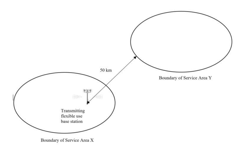
Description of figure B1
This figure shows the geometry for the sample pfd calculation. A transmitting flexible use base station is located within Service Area X. It is recommended that one find the pfd resulting from this transmitter at the boundary of a nearby Service Area Y. The distance, Dkm, to be used in this calculation is from the base station transmitter location to the boundary of Service Area Y, i.e. not from boundary to boundary. This base station transmitter has an associated power, PT, and gain in the direction of the boundary of Service Area Y, GT.
The spectral power density in dB(W/MHz) at the boundary of service area Y (Pboundary) may be calculated using freespace propagation, taking into account such factors as atmospheric losses, as follows:
Pboundary
= PT' + GT – Path Loss
= PT' + GT 20 log FMHz 20 log Dkm 32.4
= (10 + 17 20 log (3515) 20 log (50) 32.4) dB(W/MHz)
= (10 + 17 – 70.92 – 33.98 32.4) dB(W/MHz)
= 110.3 dB(W/ MHz)
where: PT'
= PT 10 log BMHz
= 20 10 log (10)
= 10 dB(W/MHz)
Then, the power flux density in dB(W/m2) in 1 MHz (pfd) may be calculated as follows:
pfd
= Pboundary 10 log Ar
= (110.3 10 log (579.9 x 10⁻⁶)) dB(W/m2) in 1 MHz
= (110.3 (32.36)) dB(W/m2) in 1 MHz
= 77.94 dB(W/m2) in 1 MHz
where: Ar
= λ2 / (4π)
= c2 / {(4π) x (FHz )2}
= (3 x 10⁸)2 / {(4π) x (3515 x 106 )2 }
= 579.9 x 10⁻⁶ m2
Note that the above calculation is presented in this form to illustrate the ease by which an alternative Path Loss calculation method can be substituted for the free-space formulation used here. This example is provided for information only and the use of other generally accepted calculation methods is permitted.
Annex C: List of FSS earth stations in the frequency band 3500-3650 MHz
The licence and location information of the FSS earth stations operating in the frequency band 3500-3650 MHz is provided in table C1.
| Licence number | Licensee information | Station location | Latitude | Longitude |
|---|---|---|---|---|
| 010001485 | INMARSAT SOLUTIONS (CANADA) INC. | Weir, Quebec | 45°56'40" | 74°31'58" |
| 010001493 | INMARSAT SOLUTIONS (CANADA) INC. | Weir, Quebec | 45°56'39.44" | 74°31'57.9" |
Annex D: Definition of exclusion zones
The exclusion zones are rectangular areas around airport runways where automated landing is authorized in Canada. The exclusion zones extend 910 metres on either side of the runway edge and 2100 metres from the runway thresholds.
The list of exclusion zones and maps depicting these zones are available for download on the Map of Exclusion Zones and Protection Zones (SRSP-520) web page.
Annex E: Provisions applicable to protection zones
E.1 Definition of protection zones
The protection zones are rectangular areas that extend from the edge of the exclusion zones defined in annex D. For each runway there are two protection zones, each extending from either end of an exclusion zone. A protection zone is 1000 metres wide and extends 6100 metres from each end of an exclusion zone.
In cases of overlap between the exclusion zone and the protection zone, the exclusion zone takes precedence.
The list of protection zones and maps depicting these zones are available for download on the Map of Exclusion Zones and Protection Zones (SRSP-520) web page.
E.2 Technical and operational requirements in protection zones
The following sections describe the technical and operational requirements for operation of outdoor stations within protection zones.
All outdoor fixed and base stations operating within the protection zones defined in section E.1 must not exceed a power flux density (pfd) limit of -38.80 dBW/m2 in 1 MHz at a height of 91.44 metres (300 feet) above ground. The pfd limit shall be satisfied 100% of the time and be evaluated for all combinations of elevation and azimuth angles above the horizon relative to the location of the fixed or base station.
Compliance with the requirements defined in this SRSP, including the pfd limit specified above, is an ongoing obligation. At any time, ISED may require a licensee to demonstrate compliance with these limits by:
- providing the Pre-Operation Report for any of its stations;
- providing detailed calculations;
- conducting site surveys; and/or
- providing any additional compliance-related information.
Despite compliance with the requirements specified above, ISED may require a licensee to implement additional measures to further enable coexistence.
E.3 Pre-Operation Report requirements
This section provides a template of the information that must be included in each Pre-Operation Report.
A single Pre-Operation Report can be generated for all stations deployed with similar radio characteristics (e.g. same antenna, radio model, e.i.r.p., downtilt, vertical scanning angles, etc.). When multiple stations are included in a single Pre-Operation Report, the coordinates of all stations must be clearly stated. In addition, the pfd limit shall be calculated using the worst-case combination of technical parameters that would be used in operation of any of the stations. For each station, any variation in technical parameters described in E.3.2 (e.g. e.i.r.p. or height above ground) must be clearly identified in the Pre-Operation Report
E.3.1 Title page
The title page should contain the assessment date, company name, site name where the station is located, name(s) of person(s) conducting the compliance study including title and signature, and date on which the Pre-Operation Report was signed.
E.3.2 Description of compliance with pfd limit
The Pre-Operation Report will describe the following elements for each station deployed in a protection zone:
- The coordinates (latitude and longitude) of the station
- Whether it is a fixed or base station
- Whether the fixed or base station is an active antenna system (AAS)
- Height of the antenna above the ground
- Mechanical (fixed) elevation and azimuth angle of antenna
- For each non-AAS fixed or base station:
- conducted power
- radiation pattern of the antenna (including back lobes)
- maximum e.i.r.p./MHz
- For each AAS fixed or base station:
- conducted power or TRP, whichever is applicable
- minimum and maximum vertical scanning angle values implemented
- maximum envelope of the radiation pattern for all vertical scanning angles
- maximum e.i.r.p./MHz (calculated using the sum of the TRP and maximum gain of the antenna)
- A technical description of the mitigation measures that will be implemented to ensure the pfd limit is respected. Technical measures may include, but are not limited to operating with a lower e.i.r.p., operating at a lower height above ground, limiting the vertical scan angle of an AAS fixed or base station, mechanical downtilt of the antenna, for AAS limiting the number of elements used to form a beam or adding additional shielding to limit emissions towards the sky.
- A demonstration, by computation or analysis, of how the mitigation measures implemented will result in the station meeting the pfd limit. The demonstration should include a description of any mathematical prediction models (e.g. propagation model) used. A sample calculation is provided in section E.4.
- A description of a plan to implement and monitor mitigation measures in practice, and the corrective actions that would be taken to remedy exceedance of the pfd limit, should it occur.
E.3.3 Compliance statement
A clear compliance statement should conclude the Pre-Operation Report. An example of a compliance statement is provided below.
Compliance Statement: I (name of individual or representative of company) attest that the information provided in this Pre-Operation Report is correct; that the technical measures described in the report will be implemented in practice as described in this Pre-Operation Report; that compliance with the pfd limit will be monitored as described in this Pre-Operation Report; and that the station is in compliance with the requirements defined in annex E of SRSP-520, issue 2.
For additions of new stations or modifications to existing stations, include the following statement:
This report replaces the Pre-Operation Repot dated: dd-mm-yyyy.
Signature:
Date:
NAME (Please print or type):
TITLE (Please print or type):
COMPANY (Please print or type):
E.3.4 Attestation requirements
At least 15 days prior to the operation of a station or the modification of an existing station within a protection zone, licensees are required to submit an attestation provided by a senior executive responsible for the installation of radio equipment (e.g. chief technical officer, VP engineering or equivalent). The attestation shall include the coordinates of the station, the protection zone number in which the station is located and the operational date of each station. The protection zone number is outlined in the first column of the table provided on the Map of Exclusion Zones and Protection Zones (SRSP-520) web page.
Each licensee is required to submit a single attestation for all stations located within any protection zones. The attestation shall include a list of all stations in the protection zone(s), the coordinates of each station, the corresponding protection zone number and the operational date of each station. When a new station or modifications to an existing station is planned, the licensee must conduct any necessary analyses to ensure technical compliance and update its Pre-Operation Report accordingly, and submit an updated attestation to ISED at least 15 days prior to the operation of the new or modified station(s). When updating the attestation to include new stations or to modify existing stations, the licensee shall indicate whether such entry is for a new station or a modification to an existing station.
The attestation must confirm that a Pre-Operation Report(s) has been completed and that the stations contained in the list of stations are in compliance with all the requirements defined in annex E of SRSP-520, issue 2.
An example of an attestation is provided below.
ATTESTATION: I, (name of individual or representative of company), attest that the Pre-Operation Report has been completed for the station(s) (name of the station, coordinates, protection zone number, operational date) listed in this Attestation; that the station(s) is in compliance with the requirements described in annex E of SRSP-520, issue 2; and that the station(s) will be installed and operated on an ongoing basis so as to be in compliance with SRSP-520, issue 2, at all times for the protection of the general public with respect to aviation safety.
For additions of new stations or modifications to existing stations, include the following statement:
This attestation contains an updated list of stations and replaces the attestation dated: dd-mm-yyyy.
Signature:
Date:
NAME (Please print or type):
TITLE (Please print or type):
LICENSEE NAME (Please print or type):
LICENCE NUMBER(S):
PHONE NUMBER:
EMAIL ADDRESS:
E.3.5 Submitting the Attestation
The attestation should be filed in an electronic format and sent to:
Spectrum Management Operations Branch
spectrumoperations-operationsduspectre@isde-isde.gc.ca
E.4 Sample pfd calculation
The following sections provide sample pfd calculations for non-AAS and AAS stations.
E.4.1 Sample pfd calculation for non-AAS station
The following example illustrates how to calculate the pfd at 91.44 metres (300 feet) above ground for a non-AAS station operating using the parameters defined in table E1. These calculated pfd values are compared to the pfd limit defined in section E.3 for operation of a fixed or base station within a protection zone. Note that the calculation in the example assumes lineofsight conditions. Where lineofsight does not exist, an appropriate propagation model that takes the nonlineofsight situation into account should be used.
| Parameter | Symbol | Value |
|---|---|---|
| Conducted power into antenna port | PT | 40 dBm/MHz |
| Antenna height above ground | HT | Base station A: 20 metres Base station B: 60 metres |
| Antenna gain at 50 degrees elevation (α) above the horizon | GT | -2.5 dBi |
| Centre frequency of block | FMHz | 3515 MHz |
Two different scenarios were evaluated:
- Base station A with a height of 20 metres above ground; and
- Base station B with a height of 60 metres above ground.
The pfd at 91.44 metres (300 feet) above the ground shall be evaluated for all combinations of elevation and azimuth angles above the horizon, as illustrated in figure E1. The pfd limit described in section E.3 must be met for all elevation and azimuth angles at 300 feet above ground. It is equivalent to find the maximum pfd value across all elevation and azimuth angles. For simplicity, it was assumed that for both base stations A and B the maximum pfd at 91.44 metres (300 feet) above the ground is occurred at 50° elevation angle with an antenna gain of -2.5 dBi in that direction.
Figure E1: Example deployment scenario for azimuth of 0 degrees and where α is elevation angle with respect to horizon
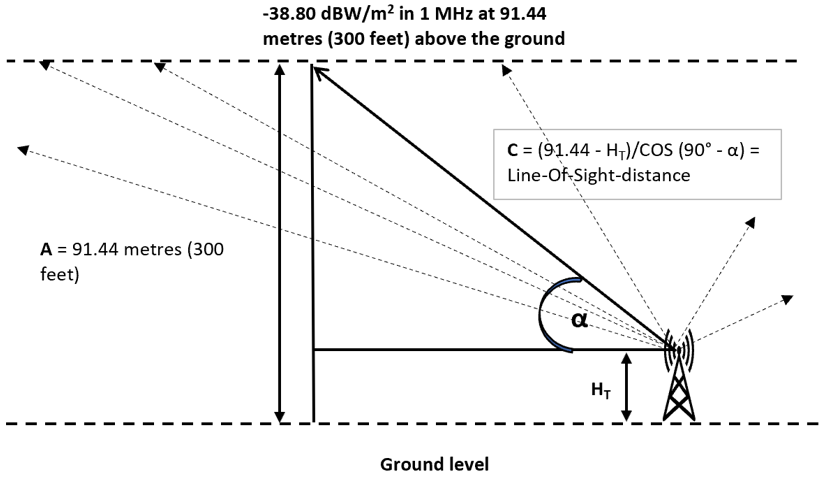
Description of figure E1
This figure shows the geometry for the sample pfd calculation. A transmitting station has an antenna placed at HT metres above ground. The pfd limit at 91.44 metres (300 feet) above the ground is -38.80 dBW/m2 in 1 MHz. The figure shows multiple lines pointing above the horizon representing different radiated power levels at different elevation angles. For the sample pfd calculation, one of those lines represents an elevation angle of α degree for which the maximum pfd occurs at 91.44 metres (300 feet) above the ground. At elevation angle α degree, an equation to determine the line-of-sight distance (C), C = (91.44 - HT)/COS(90° - α), is shown.]
The maximum power spectral density (PSD) value could be used to calculate the pfd to validate compliance with the pfd limit defined in section E.3. The following formula may be used to calculate PSD for frequency expressed in MHz and distance expressed in metres:
PSD in dBm per MHz = PT + GT – (20 log ((91.44 - HT) / (COS (90°- α))) + 20 log (FMHz) - 27.55)
The following shows the calculation of PSD and pfd for base station A:
PSD_A
= 40 + (-2.5) – (20 log ((91.44 – 20) / (Cos (90° - 50°))) + 20 log (3515) - 27.55)
= 37.5 – 82.76
= -45.26
Pfd in dB(W/m2) in 1 MHz may be calculated as follows:
Pfd_A
= Maximum PSD in dBm per MHz – 30 - 10 log Ar
= (45.26 – 30 - 10 log (579.9 x 10⁻⁶)) dB(W/m2) in 1 MHz
= (75.26 (32.36)) dB(W/m2) in 1 MHz
= 42.90 dB(W/m2) in 1 MHz
where: Ar
= λ2 / (4π)
= c2 / {(4π) x (FHz )2}
= (3 x 10⁸)2 / {(4π) x (3515 x 106 )2 }
= 579.9 x 10⁻⁶ m2
The following shows the calculation of PSD and pfd for base station B:
PSD_B
= 40 + (-2.5) – (20 log ((91.44 – 60) / (Cos (90° - 50°))) + 20 log (3515) - 27.55)
= 37.5 – 75.63
= -38.13
Pfd in dB(W/m2) in 1 MHz may be calculated as follows:
Pfd_B
= Maximum PSD in dBm per MHz – 30 - 10 log Ar
= (38.13 – 30 - 10 log (579.9 x 10⁻⁶)) dB(W/m2) in 1 MHz
= (68.13 (32.36)) dB(W/m2) in 1 MHz
= 35.77 dB(W/m2) in 1 MHz
Table E2 shows the maximum calculated pfd values for base stations A and B.
| Station | Calculated pfd value | Pfd limit in section E.3 |
|---|---|---|
| Base station A | -42.90 dBW/m2 in 1 MHz | -38.80 dBW/m2 in 1 MHz |
| Base station B | -35.77 dBW/m2 in 1 MHz | -38.80 dBW/m2 in 1 MHz |
For this example, base station A is in compliance with the pfd limit and base station B is not in compliance with the pfd limit defined in section E.3.
E.4.2 Sample pfd calculation for AAS system
The following example illustrates how to calculate the pfd at 91.44 metres (300 feet) above ground for an AAS station operating using the parameters defined in table E3. These calculated pfd values are compared to the pfd limit defined in section E.3 for operation of a fixed or base station within a protection zone. Note that the calculation in the example assumes lineofsight conditions. Where lineofsight does not exist, an appropriate propagation model that takes the nonlineofsight situation into account should be used.
| Parameter | Symbol | Value |
|---|---|---|
| Conducted power into antenna port | PT | 40 dBm/MHz |
| Antenna height above ground | HT | 20 metres |
| Antenna gain at 50 degrees elevation (α) above the horizon | GT | Base station C: 12 dBi Base station D: 0 dBi |
| Centre frequency of block | FMHz | 3515 MHz |
Two different scenarios were evaluated:
- Base station C with a maximum antenna gain of 12 dBi above horizon; and
- Base station D with a maximum antenna gain of 0 dBi above horizon.
The pfd at 91.44 metres (300 feet) above the ground shall be evaluated for all combinations of elevation and azimuth angles above the horizon, as illustrated in figure E1. The pfd limit described in section E.3 must be met for all elevation and azimuth angles. It is equivalent to find the maximum pfd value across all elevation and azimuth angles. For the purpose of simplicity of this example, it was assumed that for both base stations C and D the maximum pfd at 91.44 metres (300 feet) above the ground is occurred at 50° elevation angle with an antenna gain of 12 dBi and 0 dBi accordingly in that direction.
The maximum power spectral density (PSD) value could be used to calculate the pfd to validate compliance with the pfd limit defined in section E.3.
The following formula may be used to calculate PSD for frequency expressed in MHz and distance expressed in metres:
PSD in dBm per MHz = PT + GT – (20 log ((91.44 - HT) / (COS (90°- α))) + 20 log (FMHz) - 27.55)
The following shows the calculation of PSD and pfd for base station C:
PSD_C
= 40 + 12 – (20 log (91.44 – 20) / (Cos (90° - 50°))) + 20 log (3515) - 27.55)
= 52 – 82.76
= -30.76
Pfd in dB(W/m2) in 1 MHz may be calculated as follows:
Pfd_C
= Maximum PSD in dBm per MHz – 30 - 10 log Ar
= (30.76 – 30 - 10 log (579.9 x 10⁻⁶)) dB(W/m2) in 1 MHz
= (60.76 (32.36)) dB(W/m2) in 1 MHz
= 28.40 dB(W/m2) in 1 MHz
where: Ar
= λ2 / (4π)
= c2 / {(4π) x (FHz )2}
= (3 x 10⁸)2 / {(4π) x (3515 x 106 )2 }
= 579.9 x 10⁻⁶ m2
The following shows the calculation of PSD and pfd for base station D:
PSD_D
= 40 + 0 – (20 log (91.44 – 60) / (Cos (90° - 50°))) + 20 log (3515) - 27.55)
= 40 – 82.76
= -42.76
Pfd in dB(W/m2) in 1 MHz may be calculated as follows:
Pfd_D
= Maximum PSD in dBm per MHz – 30 - 10 log Ar
= (42.76 – 30 - 10 log (579.9 x 10⁻⁶)) dB(W/m2) in 1 MHz
= (72.76 (32.36)) dB(W/m2) in 1 MHz
= 40.40 dB(W/m2) in 1 MHz
Table E4 shows the maximum calculated pfd values for base stations C and D.
| Station | Calculated pfd value | Pfd limit in section E.3 |
|---|---|---|
| Base station C | -28.40 dBW/m2 in 1 MHz | -38.80 dBW/m2 in 1 MHz |
| Base station D | -40.40 dBW/m2 in 1 MHz | -38.80 dBW/m2 in 1 MHz |
In this example, base station C is not in compliance and base station D is in compliance with the pfd limit defined in section E.3.