
May 4, 2026
Consultation closed February 10, 2026
Publication (April 20, 2026)
Clarifications were made to Section 2.2.4 on May 4, 2026
Requirements on camera protrusion measurements for specific absorption rate compliance
Through the release of this Notice, Innovation, Science and Economic Development Canada (ISED) clarifies the requirements on specific absorption rate (SAR) assessment of camera protrusions (also known as camera bumps) in accordance with section 5.14 of RSS-102.SAR.MEAS.
1 Introduction
As per section 7.2 of the IEC/IEEE 62209-1528, an equipment under test (EUT) shall be positioned parallel to the flat phantom at the applicable separation distances. In addition, the requirements below shall be followed:
- measurement area shall not be closer than 20 mm from the phantom side wall as per clause 7.4.2 b) 2) of IEC/IEEE 62209-1528, and
- 1 g or 10 g cube shall not touch the boundary of the zoom scan volume as per clause 7.4.2 d) 3) of IEC/IEEE 62209-1528.
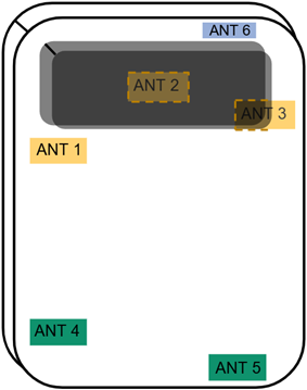
In certain smartphone designs, due to the presence of camera protrusions, as shown in Figure 1, the testing procedure must be adapted to reliably assess compliance in a repeatable/reproducible manner. The testing procedures herein outline these adapted test methods.
Figure 1: Example of extrusion on an EUT with a camera protrusion
Since IEC/IEEE 62209-1528 does not contain testing procedures specifically for EUT with camera protrusions, section 5.14 of RSS-102.SAR.MEAS was introduced to allow SAR measurements to be conducted by tilting the EUT. The following sections detail accepted testing procedures for smartphones by expanding on the requirements of section 5.14 of RSS-102.SAR.MEAS. These procedures will allow the measurement system’s probe to be positioned as close as possible to the areas near the protrusion while maintaining a consistent separation distance.
1.1 General
For smartphones with camera protrusions, the separation distance is in relation to the main body of the EUT and not from the outermost surface of the camera protrusion.
The reference plane, depicted as a red dotted line in Figure 2, corresponds to the outer surface of the main body of the EUT.
The reference point, depicted as a red dot in Figure 2, is a point located on the reference plane from which the separation distance between the EUT and the phantom shall be measured.
The separation distance between the EUT and the phantom shall be measured from the reference point on the reference plane to the phantom. The following two options are available to determine the reference point:
Option 1 – Most Conservative, Worst-Case Location (Preferred)
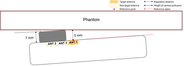
The reference point can be located on the reference plane at the position that results in the worst-case, the most conservative distance (i.e. the point on the main body of the EUT immediately adjacent to the camera protrusion where the measured distance is the closest to the required separation distance), as shown in Figure 2.
Figure 2 - EUTs with antenna(s) located near the camera protrusion
Option 2 – Measurement-Based Peak SAR Location
The reference point can be determined by performing either a full SAR (i.e., an area scan or zoom scan) or a fast SAR test to identify the peak SAR location of the target antenna, as shown in Figure 3. To do so,
- The EUT shall be positioned parallel and centered to the phantom, with the camera protrusion touching the phantom.
- The full SAR or fast SAR test shall be conducted for all required bands/modes at the configurations with the highest SAR in standalone.
- The requirements in RSS-102.SAR.MEAS section 5.1.1 shall be applied.
As shown in Figure 3, the reference point is identified at the peak SAR location of the target antenna determined from the full or fast SAR test. The respective separation distance can be measured from this reference point, rather than from the most conservative, worst-case location shown in Figure 2.
When the exact location of the target antenna is not known, Option 2 shall be used to determine the peak SAR location of the target antenna. The separation distance shall then be measured relative to that location.
Figure 3 - EUTs with antenna(s) located near the camera protrusion
2 Body-worn configurations
A list of body-worn configuration scenarios are depicted in section 2.
2.1 EUTs with small camera protrusion compared to separation distance
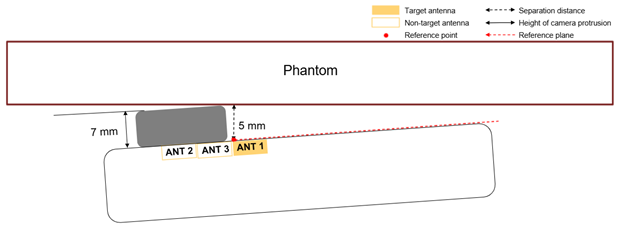
When the applicable separation distance for the exposure condition is greater than or equal to the height of the camera protrusion, the SAR measurements shall be performed with the EUT positioned parallel to the phantom.
For example, Figure 4 illustrates the EUT depicted in Figure 1 with a 3 mm camera protrusion. Since the height of the protrusion is smaller than the 5 mm separation distance, the EUT is positioned parallel to the phantom for testing.
Figure 4 - Side view of the EUT illustrated in Figure 1
2.2 EUTs with large camera protrusion compared to the separation distance
When the height of the camera protrusion is larger than the separation distance, the following procedures shall apply.
2.2.1 EUTs with antenna locations far from the camera protrusion
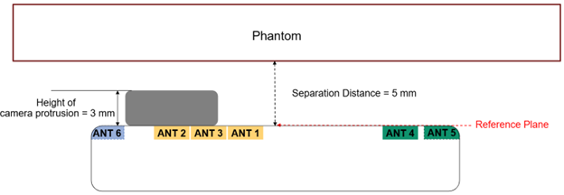
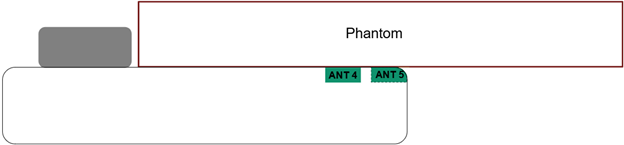
In situations where the two following conditions are met, the EUT shall be tested parallel to the phantom to assess the certain antennas, as shown in Figure 5.
- The applicable separation distance is less than the camera protrusion’s height, and
- certain antenna locations allow for testing with the phantom positioned parallel to the EUT.
Figure 5 - Side view (bottom antennas)
2.2.2 EUT(s) with antenna(s) located underneath the camera protrusion with no offset to one side
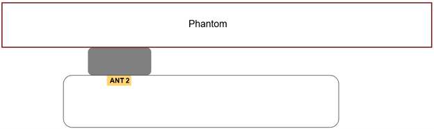
For antennas entirely underneath the camera protrusion with no offset to one side, as is the case of antenna 2 shown in Figure 1, testing shall be performed with the EUT positioned parallel to the phantom and the top part of the camera protrusion in contact with the phantom, as shown in Figure 6. Although the camera protrusion introduces a separation distance, the camera protrusion shall be in direct contact with the phantom so that the antenna underneath the camera protrusion is as close as possible to the phantom.
Figure 6 - Side view (underneath the camera protrusion)

2.2.3 EUTs with antenna(s) located near the camera protrusion
In situations where antenna(s) are located near the camera protrusion, for which testing is not possible with the phantom positioned parallel to the EUT at the required separation distance, these antennas shall be tested with the camera protrusion touching the phantom. Further, while keeping the camera protrusion in touch with the phantom, EUT shall be tilted to obtain the required separation distance for the relevant side or edge.
Note:
To ensure consistent and repeatable EUT orientation with respect to the phantom, a precision spacer (representing the separation distance) can be used to position or tilt the EUT. If the position spacer cannot be used (e.g. due to the limited separation distance between the EUT and the phantom), a positioner may be used with the adjusted angle. Once the EUT is in place in that position, all measurements should be done in that position before moving on to the next position.
Requirements pertaining to tilts for EUT:
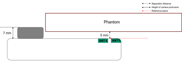
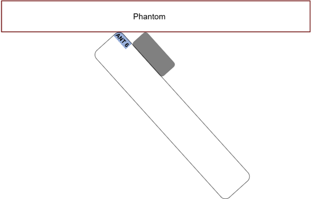
For antennas located near the bottom edge of the camera protrusion, testing shall be performed with the bottom part of the camera protrusion in contact with the phantom and the bottom part of the EUT tilted upward towards the phantom to obtain the required separation distance, as shown in Figure 7.
Figure 7- EUTs with antenna(s) located near the camera protrusion

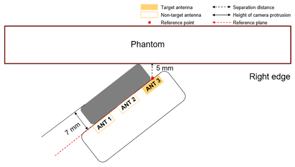
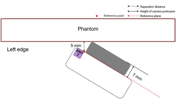
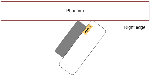
For antennas located partially underneath the camera protrusion, testing shall be performed with the corresponding side of the camera protrusion in contact with the phantom and EUT tilted along the respective edge to obtain the required separation distance, as shown in Figure 8.
Figure 8 - Front view (partially underneath the camera protrusion on the right side)
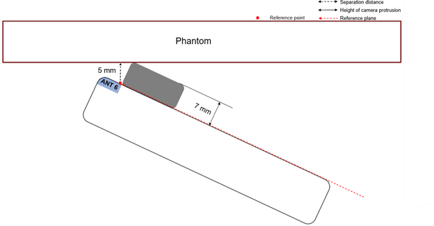
For antennas located near the top edge of the camera protrusion, testing shall be performed with the top part of the camera protrusion in contact with the phantom and the bottom part of EUT tilted downward away from the phantom to obtain the separation distance, as shown in Figure 9.
Figure 9 - Side view (top antenna)
2.2.4 EUTs with corner-mounted antennas
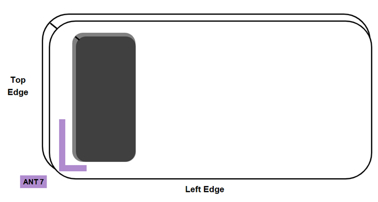
For corner-mounted antennas, when an antenna is located along two edges as shown in Figure 10, two options for compliance testing are available.
Figure 10 - Back view of corner-mounted antenna along the top and left edge
Option 1
Compliance testing shall be performed with both edges at a tilt position as illustrated in Figures 11 and 12.
Option 2 (Test Reduction)
To identify the edge(s) for compliance testing, two paths are permitted.
Path 1
The existing results from the routine SAR evaluations (without tilt) for the respective edge/side can be used to identify the edge with the highest SAR value to be tilted for compliance testing:
- When the SAR values for the two edges are less than 50% of the compliance limit, test the edge with the highest SAR value in a tilt position, or
- When at least one of the SAR values is greater than or equal to 50% of the compliance limit, and the difference between the SAR values for the two edges is:
- less than or equal to 30%, both edges shall be tested in a tilt position, or
- greater than 30%, the edge with the highest SAR value shall be tested in a tilt position.
For example, assume the EUT in Figure 10 above has 0.9 W/kg for both the top and left edges from the routine SAR evaluation. Since both the SAR values are greater than 50% of the compliance limit and the difference between the two edges is less than 30%, both edges of the EUT shall be tested in a tilt position. Assuming the same EUT would instead have 1.1 W/kg and 0.8 W/kg for the top and left edges respectively, testing shall only be required to the top edge in a tilt position.
Path 2
Measurement using a full SAR area scan or fast SAR array scan in the tilt positions to the respective edges can be conducted to identify the edge with the highest SAR value for compliance testing:
- The EUT shall be positioned parallel and centered to the phantom, with the camera protrusion touching the phantom and tilted at the respective edge.
- The full SAR or fast SAR test shall be conducted for all required bands/modes at the configurations with the highest SAR in standalone mode.
- The requirements in section 5.1.1 of RSS-102.SAR.MEAS shall be applied.
For example, assume the EUT in Figure 10 above has 1g SAR values from the fast SAR array scan for the top and left edges at the tilt positions of 1.1 W/kg and 0.8 W/kg respectively. Since the top edge has the highest SAR value, only the top edge in a tilt position shall be required for compliance testing.
If implementing Path 2, a zoom scan is mandatory for any configuration where the SAR results are greater than or equal to 75% of the applicable compliance limit.
As per Section 5.1.1 of RSS-102.SAR.MEAS, Fast SAR is allowed to be used to identify the worst case SAR test configurations (relative SAR measurements). Whether the SAR values from routine SAR evaluation or fast SAR is used, once the worst-case edge has been identified, compliance testing (absolute SAR measurements) shall always subsequently be measured with a full SAR system.
When the same frequency band is used across different technologies, the results of identifying the tilt position from Option 2 may be applied across those technologies. For example, when both the top and left tilt positions are evaluated for an LTE frequency band and the top tilt is identified as the worst case by more than 30%, the top tilt may be used for compliance testing of that band for 5G without requiring additional evaluation of the left tilt.
Figure 11 – Top tilt position of EUT from Figure 10
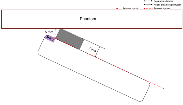
Figure 12 – Left edge tilt position of EUT from Figure 10
3 Limb-worn configurations
For limb-worn configurations, as per RSS-102.SAR.MEAS, the separation distance shall be 0 mm. The procedures in section 3 shall be used.
Note:
Section 3 for limb-worn configurations is also applicable to body-worn configurations requiring testing at 0 mm.
3.1 EUTs with antenna(s) located far from the camera protrusion
EUTs with a camera protrusion shall be tested at touch position (0 mm) in parallel to the phantom if the antenna locations allows the phantom to be positioned in parallel to the EUT, as shown in Figure 13.
Figure 13 - Side view (bottom antennas)
3.2 EUTs with antenna(s) located near the camera protrusion
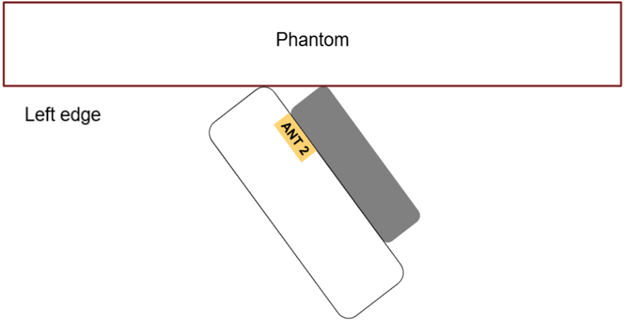
For antennas located near the camera protrusion, testing shall be performed with the corresponding side of the camera protrusion and EUT in contact with the phantom along the respective edge to obtain the touch position.
Figure 14 - Bottom view (left antenna)
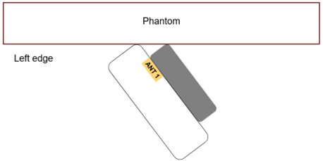
Figure 15 - Bottom view (right antenna)
3.3 EUTs with antenna(s) located underneath the camera protrusion
There are two types of EUTs with antenna(s) located underneath the camera protrusion.
3.3.1 EUT(s) with antenna(s) located underneath the camera protrusion with no offset to one side
When all antennas are entirely underneath the camera protrusion with no offset to one side, as is the case of antenna 2 shown in Figure 1, testing shall be performed with the EUT positioned parallel to the phantom and the top part of the camera protrusion in contact with the phantom, as shown in Figure 16. Although the camera protrusion creates a separation distance, the camera protrusion shall be in direct contact with the phantom so that the antenna underneath the camera protrusion is as close as possible to the phantom.
Figure 16 - Side view of the EUT (antenna is centered underneath the camera protrusion)
3.3.2 EUTs with antenna(s) located underneath the camera protrusion with offset to one side
In cases where the antennas are entirely underneath the camera protrusion, with offset to one side as shown in Figure 17, the required testing becomes the same as what is required for antennas located near the camera protrusion, as outlined in section 3.2 this notice. Testing shall be performed with the corresponding side of the camera protrusion and EUT in contact with the phantom along the respective edge to obtain a position as close as possible to the touch position as depicted in Figure 18.
Figure 17 Back view of EUT with entire antenna underneath the camera protrusion
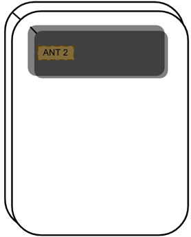
Figure 18 Bottom view of Figure 17
3.4 EUTs with antenna(s) located on the top edge
For antennas on the top edge, testing shall be conducted with the top part of the camera protrusion and EUT in contact with the phantom, as shown in Figure 19.
Figure 19 - Side view (top antenna)
3.5 EUTs with corner-mounted antennas
For corner-mounted antennas, the same procedure as outlined in section 2.2.4 of this notice shall be followed; however with a separation distance of 0 mm.
4 Consideration for simultaneous spatially separated transmitters evaluations
Compliance of an EUT with multiple transmitters capable of simultaneous transmission shall continue to be assessed in accordance with section 5.5 of RSS-102.SAR.MEAS.
Evaluations for spatially separated transmitters, based on the SAR to peak location separation ratio (SPLSR) method, where testing is conducted at a tilt, shall be performed as follow:
A full SAR (i.e., area scan or zoom scan) or fast SAR test for all required bands/modes at the configurations with the highest SAR in standalone mode, with the EUT positioned parallel centered to the phantom, and with the protrusion touching the phantom, shall be performed.
When the results are above 75% of the applicable compliance limit or when the SPLSR is within 75% of the SPLSR limit, only the coordinates from the zoom scan shall be used.
- The EUT shall be positioned parallel and centered to the phantom, with the camera protrusion touching the phantom and tilted at the respective edge.
- The full SAR or fast SAR test shall be conducted for all required bands/modes at the configurations with the highest SAR in standalone.
- The requirements in section 5.1.1 of RSS-102.SAR.MEAS shall be applied.
- If the difference between the SAR values for the two edges is greater than 30% or less than half (i.e., 50%) of the compliance limit, the back side of the EUT shall be tested for the edge with the highest SAR value in a tilt position, or
- If the difference between the SAR values for the two edges is less than or equal to 30% or greater than half of the compliance limit, both edges shall be tested in a tilt position.
- The EUT shall be positioned parallel and centered to the phantom, with the camera protrusion touching the phantom.
- The full SAR or fast SAR test shall be conducted for all required bands/modes at the configurations with the highest SAR in standalone.
- The requirements in RSS-102.SAR.MEAS section 5.1.1 shall be applied.
-
- Figure 14 illustrates the tilt position for an antenna near to the camera protrusion on the left side, with the left edge of the EUT positioned towards the phantom.
-
- Figure 15 illustrates the tilt position for an antenna partially underneath or overlapping the camera protrusion on the right side, with the right edge of the EUT positioned towards the phantom.
-
- The coordinate locations of the peak SAR values from the full SAR or fast SAR tests, with the EUT positioned parallel centered to the phantom, shall be used to calculate the peak SAR separation distance in the SPLSR equation.
- The SAR values measured at the tilt positions, as described in Sections 2 and 3 of this Notice, shall be used in the SPLSR equation.
- The requirements in RSS-102.SAR.MEAS section 5.1.1 shall be applied.