
Issue 3
December 2008
Note (July 5, 2023): Standard Radio System Plan SRSP-520, Technical Requirements for Fixed and/or Mobile Systems, Including Flexible Use Broadband Systems, in the Band 3450-3650 MHz, issue 1, dated July 2020 replaced SRSP-303.4, Technical Requirements for Fixed Wireless Access Systems Operating in the Band 3475-3650 MHz, issue 3.
However, specific provisions of SRSP-303.4, issue 3, continue to apply for fixed spectrum licences issued prior to June 2019, and for fixed spectrum licences issued after June 2019 as a result of the conversion of existing fixed spectrum licences from Tier 4 to Tier 5 licence areas.
In addition, effective immediately, in order to enable coexistence with radio altimeters in the 4200-4400 MHz band, the following text contained in section 5.1 no longer applies: “However, higher e.i.r.p. may be permitted if technical justification is provided.” Editorially, this change will be reflected in a future issue of this SRSP.
Preface
Issue 3 of SRSP -303.4 has been released to provide additional information on coexistence between FWA systems and other radio services sharing the same and adjacent spectrum. This SRSP replaces SRSP-303.4, Issue 2.
The following are the main changes:
- The frequency change in the title has been modified to reflect the spectrum that is actually available for licensing. (Note, however, that the spectrum limits per Section 4.1.1 have not been changed).
- Information has been added on Canadian footnotes C18 and C20 (Section 2.7).
- Clarification has been provided regarding spectrum usage and coordination obligations vis-a-vis the United States (Sections 2.8 and 6.1).
- Clarification has been provided regarding spectrum usage and coordination obligations vis-a-vis the Fixed-Satellite Service (Sections 2.9, 2.10 and 7).
- A number of other editorial updates and improvements have been made.
Issued under the authority of
the Minister of Industry
![]()
Marc Dupuis
Acting Director General
Spectrum Engineering Branch
Contents
- Intent
- General
- Related Documents
- Radio Frequency Channel Arrangements
- Technical Criteria
- FWA to FWA Frequency Coordination
- Co‑existence with Fixed Satellite Service Earth Stations
- Appendix A — Sample pfd Calculation
- Appendix B — Parameters for Coordination
- Appendix C — Process to Determine Whether Coordination is Required for Cases Where a Sharing Agreement Between the Licensees has not been Concluded
1. Intent
1.1 This Standard Radio System Plan (SRSP) states the minimum technical requirements for the efficient use of the frequency band 3475-3650 MHz by the fixed service for Fixed Wireless Access (FWA)Footnote 1 including point‑to‑point applications.
1.2 This SRSP specifies technical characteristics relating to efficient spectrum usage only, and is not to be regarded as a comprehensive specification for equipment design and/or selection.Footnote 2
2. General
2.1 Revision of this SRSP will be made as required.
2.2 Radio systems conforming to these technical requirements will be given licensing priority over non‑standard radio systems operating in this band.
2.3 The arrangements for non‑standard systems are outlined in Spectrum Utilization Policy Gen, General Information Related to Spectrum Utilization and Radio System Policies (SP-GEN).
2.4 Although a radio system conforms to the requirements of this SRSP, modifications may be required whenever harmful interferenceFootnote 3 is caused to other radio stations or systems.
2.5 When potential conflict between radio systems cannot be resolved by the parties concerned, Industry Canada should be advised. After consultation with these parties, Industry Canada will determine what modifications need to be made and establish a schedule for these modifications in order to resolve the conflict.
2.6 Industry Canada will require applicants and/or licensees to cooperate with each other in the selection and use of the assigned frequencies in order to minimize interference, thereby obtaining the most effective use of the authorized spectrum.
2.7 It should be noted that the fixed service shares the band 3475-3650 MHz with other services in accordance with the Canadian Table of Frequency Allocations, with associated footnotes C18 (CAN-03)Footnote 4 and C20 (CAN-03)Footnote 5 and spectrum utilization policies.
2.8 It should be noted that airborne and ship‑based radars in the radiolocation service may also operate in this band in Canada, the United States near the Canada/United States border and in coastal waters, particularly in southern British Columbia and the Atlantic Provinces. FWA systems will not be protected from interference caused by radiolocation systems.
2.8.1 The Department has concluded that the potential for interference in the band 3475-3650 MHz is minimal throughout most of Canada (some exceptions are described in Sections 4.1.4 and 4.1.5); however, the possibility of occasional interference to FWA systems from radiolocation operations cannot be completely ruled out. There remains a small potential throughout Canada for such interference to cause a reduction in performance of FWA systems. In cases of national security, this band may experience increased interference due to radiolocation activities throughout Canada.
2.8.2 The radiolocation service in the band 3400‑3500 MHz has a primary allocation and is limited in Canada to government use. In the band 3450‑3500 MHz, the fixed service is subject to Canadian footnote C15 (CAN97)Footnote 6 in the Canadian Table of Frequency Allocations. The fixed service allocation has been suppressed in the band 3400‑3450 MHz.
2.8.3 In the United States, the band 3400‑3650 MHz is allocated to the radiolocation service on a primary basis for government use.
2.8.4 The 3475‑3650 MHz band is not designated for FWA use in the United States.
2.9 Licensees and/or applicants should be aware that the 3475‑3650 MHz frequency band is used by:
- FWA systems in the band 3400‑3550 MHz licensed under SRSP-303.4, Issue 1;
- point‑to‑point microwave systems in the band 3500‑3700 MHz licensed under SRSP-303.5, Issue 4;Footnote 7 and
- a limited number of receive Earth stations in the fixed‑satellite service in the band 3500‑3700 MHz, typically those that communicate with foreign‑licensed satellites.
2.10 FWA licensees and/or applicants planning to operate in the band 3475‑3650 MHz should be aware that the 3700‑4200 MHz frequency band is used by receive Earth stations in the fixed‑satellite service.
2.11 Fixed Wireless Access equipment must be certified in accordance with Radio Standards Specification 192 (RSS-192), Fixed Wireless Access Equipment Operating in the Band 3450‑3650 MHz.
3. Related Documents
The current issues of the following documents are applicable, and available on the Spectrum Management and Telecommunications website at: http://www.ic.gc.ca/spectrum.
General Information Related to Spectrum Utilization and Radio Systems Policies
Policy and Licensing Procedures for the Auction of Spectrum Licences in the 2300 MHz and 3500 MHz Bands
Proposed Spectrum Utilization Policy, Technical and Licensing Requirements for Wireless Broadband Service (WBS) in the band 3650‑3700 MHz
Expansion of Spectrum for Fixed Wireless Access in the 3500 MHz Range
Restructuring the Spectrum in the Band 3400‑3650 MHz to More Effectively Accommodate Fixed Wireless Access and Radiolocation Services
Fixed Wireless Access Equipment Operating in the Band 3450‑3650 MHz
![]()
CPC — Client Procedures Circular
SP — Spectrum Utilization Policy
SRSP — Standard Radio System Plan
TRC — Telecommunications Regulation Circular
4. Radio Frequency Channel Arrangements
4.1 The band 3400‑3700 MHz is divided into frequency blocks of 25 MHz each, and designated as follows:
| BLOCK A | 3400‑3425 MHz |
|---|---|
| BLOCK B | 3425‑3450 MHz |
| BLOCK C | 3450‑3475 MHz |
| BLOCK D | 3475‑3500 MHz |
| BLOCK E | 3500‑3525 MHz |
| BLOCK F | 3525‑3550 MHz |
| BLOCK G | 3550‑3575 MHz |
| BLOCK H | 3575‑3600 MHz |
| BLOCK J | 3600‑3625 MHz |
| BLOCK K | 3625‑3650 MHz |
| BLOCK L | 3650‑3675 MHz |
| BLOCK M | 3675‑3700 MHz |
4.1.1 In accordance with DGTP-006-03, DGTP-002-03, SP 3400-3700 MHz and the Policy and Licensing Procedures for the Auction of Spectrum Licences in the 2300 MHz and 3500 MHz Bands, the band 3475‑3650 MHz is available for licensing Fixed Wireless Access systems, including point‑to‑point applications. The frequency blocks available for licensing will depend on the system's location within Canada as follows. These blocks may be sub‑divided by the licensee.
- Existing FWA systems licensed under SRSP-303.4, Issue 1, are grandfathered and may continue to operate as per their existing licences.Footnote 8 These systems were licensed in Blocks A through F (typically A and E or B and F, for systems with 100 MHz duplex spacing). Base‑to‑subscriber links for FDD systems were in the upper block, e.g. blocks E or F of each pair. All new FWA systems will be licensed under SRSP-303.4, Issue 3.
- No new FWA systems will be licensed in Blocks A through C or in Blocks L and M.
- Throughout Canada, except as noted below, Blocks D through K are available for licensing for FWA systems.
- On Vancouver Island and the Gulf Islands, FWA applicants will be required to demonstrate substantial obstruction loss due to terrain blockage preventing line‑of‑sight paths to their proposed FWA service area from either the Pacific Ocean or the Straits of Georgia and Juan de Fuca to mitigate interference from coastal radiolocation operations. Such systems may be authorized on a case‑by‑case basis in Blocks E through K.
4.1.2 Frequency blocks are paired as follows:
- Blocks D and H
- Blocks E and J
- Blocks F and K
- Block G
This block structure is illustrated below:
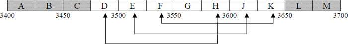
4.1.3 Frequency blocks available for licensing are symmetrically paired to facilitate Frequency Division Duplex (FDD) systems. For these systems, the base‑to‑subscriber links are preferred in the lower block, i.e. blocks D, E and F, and the subscriber‑to‑base links are preferred in the upper block. Time Division Duplex (TDD) systems may operate in either block of each pair, or in Block G. Licensees using TDD technology are required to provide sufficient guard bands consistent with the out-of-band emission mask in RSS-192, which may be, typically, one RF channel width at each block edge, to ensure compatibility with licensees operating in adjacent frequency blocks.
4.1.4 The cities of Halifax, Dartmouth and Vancouver, and nearby coastal areas including those communities that are along the Strait of Georgia, are susceptible to an increased potential of interference in all spectrum blocks. FWA systems may be subject to degraded performance conditions due to occasional radar interference. Consequently, the Department recommends that FWA operators employ interference mitigation measures should they wish to limit their susceptibility to this interference. For example, Frequency Division Duplex (FDD) systems could use the higher duplex frequencies for hub station receive operation or operators could position hub station antennas so as to avoid line‑of‑sight paths from the Atlantic Ocean or from the Straits of Georgia and Juan de Fuca. If these solutions are not possible then FWA operators shall not provide critical services to customers, such as public emergency (e.g. 911) and public safety.
4.1.5 The potential for interference to FWA systems on Vancouver Island, including the Gulf Islands, is of particular concern. Because of this concern, FWA systems will only be authorized where good shielding from mountainous terrain exists, particularly in inland locations, to mitigate interference from radiolocation operations. Such systems will only be authorized in the band 3500‑3650 MHz (i.e. frequency blocks E through K). The interference mitigation measures described in 4.1.4 are also recommended. Because of the high potential for interference in these areas, no systems in these areas shall offer critical services such as public emergency (e.g. 911) and public safety to consumers.
5. Technical Criteria
5.1 Maximum Equivalent Isotropically Radiated Power
Hub and subscriber/remote station transmissions should not exceed +32 dBW equivalent isotropically radiated power (e.i.r.p.) per RF channel. However, higher e.i.r.p. may be permitted if technical justification is provided.
5.2 Out-of-Block Emission Limits
The out‑of‑block emission limits are specified in RSS-192.
6. FWA to FWA Frequency Coordination
6.1 Same frequency block coordination is required between licensed service areasFootnote 9 where the shortest distance between respective service area boundaries is less than 60 km .Footnote 10 Note that, as per Sections 2.8.3 and 2.8.4, no coordination is required with the United States in this band.
6.2 Licensees are encouraged to arrive at mutually acceptable sharing agreements that allow for the provision of service of each licensee within their service area to the maximum extent possible.
6.3 Licensees are expected to take full advantage of interference mitigation techniques such as antenna discrimination, polarization, frequency offset, shielding, site selection, and/or power control to facilitate the coordination of systems.
6.4 If a licence is transferred, assigned or reissued, any existing agreement(s) that formed the basis of coordination shall continue to apply with respect to the new licensee unless a new agreement is reached.
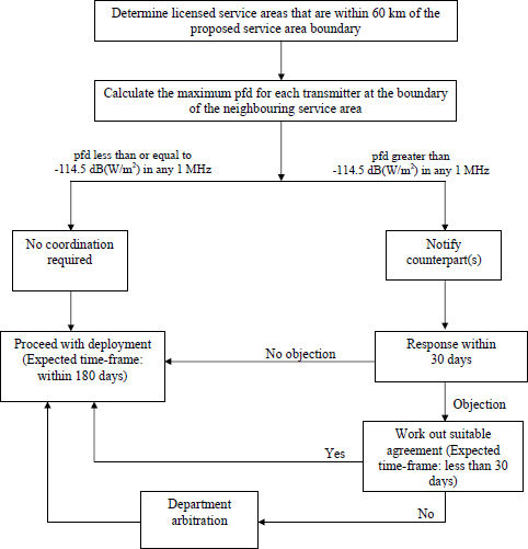
6.5 In circumstances where a sharing agreement does not exist or has not been concluded between licensees, the following coordination process shall apply:Footnote 11
6.5.1 Licensees are required to calculate the power flux‑density (pfd) at the service area boundary of the neighbouring service area(s) of the transmitting facilities. Pfd is calculated using accepted engineering practices, taking into account such factors as propagation loss, antenna directivity toward the service boundary, and the curvature of the Earth. The pfd value used shall be the maximum value calculated for elevation points between 0 m and 500 m above local terrain at the service area boundary. See Appendix A for a sample pfd calculation.
6.5.2 Deployment of facilities that generate a pfd less than or equal to –114.5 dB(W/m2) in any 1 MHz at the neighbouring service area boundaries is not subject to any coordination requirements.
6.5.3 Deployment of facilities that generate a pfd greater than –114.5 dB (W/m2) in any 1 MHz is subject to successful coordination between the affected licensees in accordance with the following process:
6.5.3.1 Licensees must notify the respective other licensee(s) of their intention to deploy the facility(ies), and submit the information necessary to conduct an interference analysis. A list of suggested data elements is given in Appendix B.
6.5.3.2 The recipient of the coordination proposal must respond by registered mail (or another mutually acceptable method) within 30 calendar days of receipt to indicate any objection to deployment of the proposed facilities. If no objection is raised within that time frame, then deployment of facilities may proceed.
6.5.3.3 If an objection is raised, the respective licensees must work in collaboration to develop a suitable agreement between them before the deployment of facilities. It is expected that the time frame to develop such an agreement should not exceed 30 calendar days.
6.5.3.4 Proposed facilities must be deployed within 180 calendar days of the conclusion of coordination, otherwise coordination must be re‑initiated as per Section 6.5.3.
6.5.4 In the event that a mutually acceptable agreement cannot be concluded between licensees, then the licensee seeking coordination may ask the Department to facilitate resolution of the case. A station that requires coordination shall not be placed in operation until an agreement has been reached.
6.5.5 Licensees may exceed a pfd level of –114.5 dB(W/m2) in any 1 MHz bandwidth at their service area boundary on a provisional basis where there is no neighbouring licensee within 60 km. However, in the event that a new licensee is authorized within 60 km, the existing licensee will be required to coordinate to a pfd level of –114.5 dB(W/m2) in any 1 MHz bandwidth at the new licensee's service area boundary, unless otherwise agreed with the new licensee.
6.5.6 FWA stations will require further coordination if proposed modifications:
- result in a pfd at or beyond the other service area boundary exceeding -114.5 dB(W/m2) in any 1 MHz bandwidth;
- involve operation on frequencies not previously coordinated; or
- change the polarization.
6.6 While coordination between adjacent frequency-block licensees operating in the same vicinity may not be required in most cases, licensees may agree to coordinate certain installations to avoid interference.
6.7 All results of analyses on pfd and agreements made between licensees must be retained by the licensees and made available to the Department upon request.
7. Co‑existence with Fixed Satellite Service Earth Stations
In Canada, the FSS operates in the band 3700‑4200 MHz. A limited number of Earth stations may also operate in the band 3500‑3700 MHz.
7.1 Licensees planning to establish FWA systems in the vicinity of an existing FSS earth station operating in the band 3500‑3700 MHzFootnote 12 are required to coordinate with Earth Station licensee.
7.2 Unwanted emissionsFootnote 13 generated by FWA systems compliant with this SRSP and RSS-192 may potentially interfere with the FSS in the 3700‑4200 MHz band due to the receiver sensitivity characteristics of satellite earth stations. Licensees planning to establish FWA systems are required to consult the list of licensed FSS earth station receivers in the 3700‑4200 MHz band using the "Radio Frequency Search" tools located on Industry Canada's website at http://sd.ic.gc.ca/ and consult the FSS operator when planning to deploy a system in the vicinityFootnote 14 of a licensed earth station. Potential interference should be resolved through mutual arrangements between the affected parties.
Appendix A — Sample pfd Calculation
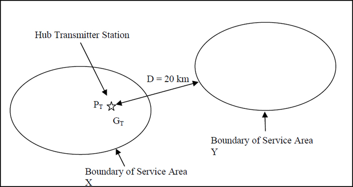
The following example illustrates how the pfd level at the service area boundary may be determined.Footnote 15
| Parameter | Symbol | Value |
|---|---|---|
| Hub transmitter power into the antenna | PT | -10 dBW |
| Channel bandwidth | B | 3.5 MHz |
| Transmitter antenna height above ground | HT | 30 metres |
| Transmitter antenna gain (maximum gain toward the service area boundary at any elevation point 0 – 500 m above average terrain) | GT | 17 dBi |
| Centre frequency of block | FMHz | 3587.5 MHz |
| Distance from hub transmitter to the boundary of the service area Y | Dkm | 20 km |
The spectral power density in dB(W/MHz) at the boundary of Service Area Y (Pboundary) may be calculated using free‑space propagation, taking into account such factors as atmospheric losses, as follows:
Pboundary
= PT' + GT – Path Loss
= PT' + GT - 20 log F MHz - 20 log D km - 32.4
= (-15.4 + 17 - 20 log (3587.5) - 20 log (20) - 32.4) dB( W / MHz )
= (-15.4 + 17 - 71.1 - 26.0 - 32.4) dB( W / MHz )
= -127.9 dB( W / MHz )
where: PT'
= PT - 10 log B MHz
= -10 - 10 log (3.5)
= -15.4 dB( W / MHz )
Then, the power flux-density in dB( W /m2) in 1 MHz ( pfd ) may be calculated as follows:
pfd
= Pboundary - 10 log Ar
= (-127.9 - 10 log (556.5 x 10⁻⁶)) dB( W/m2 ) in 1 MHz
= (-127.9 - (-32.5)) dB( W /m2) in 1 MHz
= -95.4 dB( W/m2 ) in 1 MHz
where: Ar
= λ2 / (4π)
= c2 / (4πFHz2)
= (3 x 10⁸)2 / (4π x (3587.5 x 106)2 )
= 556.5 x 10⁻⁶ m2
Note: The calculation is presented in this form to illustrate the ease by which an alternative Path Loss calculation method can be substituted for the free space formulation used here. This example is provided for information only and the use of other generally accepted calculation methods is permitted.
Appendix B — Parameters for Coordination
List of parameters that should be provided:
- Contact information (Corporate name/Mailing address/Phone/Fax/Email)
- Location of transmitter (Community/Province)
- Geographical coordinates of transmitting antenna
- e.i.r.p. (dBW)
- Ground elevation and antenna height above ground (m)
- Centre frequency (MHz)
- Polarization
- Antenna pattern/tabulation of the pattern
- Azimuth of the maximum antenna gain
- Frequency offset information for analog systems
- Bandwidth and emission designation
Note: More parameters may be provided, if needed, for the coordination process.
Appendix C — Process to Determine Whether Coordination is Required for Cases Where a Sharing Agreement Between the Licensees has not been Concluded
[Description of Figure 1]
Footnotes
- Footnote 1
-
Fixed Wireless Access generally refers to the use of fixed or nomadic radios to provide access to a public telecommunications network for telephone and/or data services serving residential and business communities. These systems may also provide for private networks.
- Footnote 2
-
This band has been the subject of a competitive (auction) licensing process. More details are available at: http://www.ic.gc.ca/eic/site/smt-gst.nsf/eng/h_sf05996.html.
- Footnote 3
-
For the purpose of this SRSP, "harmful interference" means interference that endangers the functioning of a radionavigation service or other safety services, or seriously degrades, obstructs, or repeatedly interrupts a radiocommunication service operating in accordance with regulations and technical requirements laid down by Industry Canada under the Radiocommunication Act.
- Footnote 4
-
4C18 (CAN-03): The band 3450‑3650 MHz is designated for fixed wireless access applications under the fixed service allocation.
- Footnote 5
-
5C20 (CAN-03): In the band 3500‑3650 MHz, the fixed‑satellite earth‑stations will be located in areas so as not to constrain the implementation of fixed wireless access systems.
- Footnote 6
-
6C15 (CAN97): In certain regions of Canada, the radiolocation service has priority over the fixed service. Consequently, the deployment of fixed systems will be subject to successful coordination with radar facilities operated by the Government of Canada.
- Footnote 7
-
More details can be found in the current issue of SRSP-303.7.
- Footnote 8
-
FWA systems licensed under SRSP-303.4, Issue 1, are grandfathered in accordance with Industry Canada's policy announced in DGTP-002-03 and DGTP-006-03.
- Footnote 9
-
This includes grandfathered FWA systems licensed under SRSP-303.4, Issue 1.
- Footnote 10
-
In the event a licensee uses sites at very high elevations relative to local terrain that could produce interference to FWA service areas beyond 60 km, the Department recommends coordination with the affected licensee(s).
- Footnote 11
-
This process is illustrated graphically in Appendix C of this document.
- Footnote 12
-
As a starting point in determining potential interference, this can be considered to be a radius of 150 km around the earth station. Currently, the only such stations are located in Weir, Quebec at latitude 45° 56' 40" North and longitude 74° 31' 58" West.
- Footnote 13
-
As defined in RSS -192.
- Footnote 14
-
As a starting point in determining potential interference, this can be considered to be a radius of 25 km around the FSS earth station.
- Footnote 15
-
It should be noted that the calculation in the example assumes line‑of‑sight conditions. Where line‑of‑sight does not exist, an appropriate propagation model that takes the non‑line‑of‑sight situation into account should be used.
Image Descriptions
Section 4.1.2 — Figure 1
Figure 1 — This figure illustrates the radio frequency block structure described in Section 4.1. Blocks D and H, E and J, as well as F and K, are paired together to facilitate systems using frequency division duplexing.
Appendix A — Figure 1
This figure shows the geometry for the sample pfd calculation. A hub transmitter station is located within Service Area X. It is recommended that one find the pfd resulting from this transmitter at the boundary of a nearby Service Area Y. The distance, Dkm, to be used in this calculation is from the hub transmitter location to the boundary of Service Area Y, i.e. not from boundary to boundary. This hub transmitter has an associated power, PT, and gain in the direction of the boundary of Service Area Y, GT.
Appendix C — Figure 1
This figure provides a flow chart to illustrate the FWA to FWA frequency coordination process. This process is fully described in Section 6.