
2nd edition
October 2022
Gazette Notice SMSE-016-22
Contents
- 1. Scope
- 2. Purpose and Application
- 3. Normative references
- 4. Definitions, abbreviations/acronyms, and symbols/units
- 5. General requirements for compliance assessment of EUTs operating from 3 kHz to 10 MHz 5
- 6. Measurement-based assessments against the basic restrictions
- 7. Measurement-based assessments against the reference levels
- 8. Computational assessments
- 9. Total exposure
- 10. RF exposure technical brief
- Annex A: Summary of required information for the RF exposure technical brief
- Annex B: Spatial averaging for whole-body exposure assessments
- Annex C: Additional requirements for measurement-based, time-domain assessments against the SAR-based reference levels
- Annex D: Additional requirements for WPT implementations
- Annex E: Additional requirements for various device types
- Annex F: Bibliography
Preface
This Innovation, Science and Economic Development Canada (ISED) supplementary procedure describes the technical requirements and assessment procedures for demonstrating compliance of radiocommunication apparatus with the radiofrequency (RF) exposure limits outlined in Radio Standards Specification RSS-102, Radio Frequency (RF) Exposure Compliance of Radiocommunication Apparatus (All Frequency Bands), from 3 kHz to 10 MHz. It applies to all radiocommunication apparatus producing RF emissions in this range. It also applies to some interference-causing equipment, specifically Industrial, Scientific and Medical equipment.
Supplementary Procedure SPR-002, issue 2, Supplementary Procedure for Assessing Compliance of Equipment Operating from 3 kHz to 10 MHz with RSS-102, replaces SPR-002, issue 1, Supplementary Procedure for Assessing Compliance with RSS-102 Nerve Stimulation Exposure Limits, dated September 2016.
SPR-002, issue 2, constitutes a significant revision relative to issue 1. At a high level, the major changes can be summarized as follows:
- the scope has been broadened to include:
- assessments against the RF exposure limits to prevent both nerve stimulation and thermal effects
- assessments against both the reference levels and basic restrictions
- measurement-based and computational assessments
- the requirements provided for measurement-based assessments against the reference levels have been modernized to accommodate new devices and technologies
- the relaxation factors for limb exposure in assessments against the reference levels have been revised
- IEC/IEEE 62704-1 and 62704-4 have been used as part of the foundation for the computational assessment approach, and are incorporated by reference
- an annex providing specific and detailed requirements for wireless power transfer implementations has been added, with an emphasis on portable device and electric vehicle charging
Issued under the authority of
the Minister of Innovation, Science and Industry
Martin Proulx
Director General
Engineering, Planning and Standards Branch
Inquiries may be submitted by one of the following methods:
- online using the General Inquiry form (in the form, select the Directorate of Regulatory Standards radio button, identify (RSS) Radio Standards Specification (e.g., RSS-102) as the standard/procedure and specify “SPR-002” in the General Inquiry field)
- by mail to the following address:
Innovation, Science and Economic Development Canada
Engineering, Planning and Standards Branch
Regulatory Standards Directorate
235 Queen St
Ottawa ON K1A 0H5 - by email to consultationradiostandards-consultationnormesradio@ised-isde.gc.ca
Comments and suggestions for improving this standard may be submitted online using the Standard Change Request form or by mail or email to the above addresses.
All ISED publications related to spectrum management and telecommunications are available on the Spectrum Management and Telecommunications website.
1. Scope
Supplementary Procedure SPR-002, issue 2, sets out methods for assessing compliance of equipment operating in the frequency range from 3 kHz to 10 MHz with the radio frequency (RF) exposure limits to prevent nerve stimulation (NS) and thermal effects outlined in Radio Standards Specification RSS-102, Radio Frequency (RF) Exposure Compliance of Radiocommunication Apparatus (All Frequency Bands).
The requirements within this document also apply to Type 1 wireless power transfer (WPT) source subassemblies, classified as interference-causing equipment, specifically Industrial, Scientific and Medical (ISM) equipment, in order to demonstrate compliance with Health Canada’s Safety Code 6.
1.1 Transition Period
This document will be in force upon publication on Innovation, Science and Economic Development Canada’s (ISED) website. However, a transition period of 12 months following its publication will be provided, within which certification using the requirements of SPR-002, issue 2 or issue 1, will be accepted. After this period, only applications for certification of equipment using SPR-002, issue 2, will be accepted and equipment manufactured, imported, distributed, leased, offered for sale, or sold in Canada shall comply with this issue.
A copy of SPR-002, issue 1, may be requested by email at consultationradiostandards-consultationnormesradio@ised-isde.gc.ca.
2. Purpose and application
This Supplementary Procedure to RSS-102 provides general requirements for both measurement-based and computational assessments of RF exposure in the range of 3 kHz to 10 MHz, as well as the combination of exposure contributions from multiple transmitters and/or multiple frequencies.
With the exception of annex F, the annexes of SPR-002 are normative, providing additional requirements related to spatial averaging and assessment methods for WPT implementations (e.g. to enable portable device or electric vehicle (EV) charging) as well as a variety of common device types (e.g. enabling electronic article surveillance, metal detection, radiofrequency identification, tire pressure monitoring and vehicle security).
ISED may consider assessment methods not covered by SPR-002 or the normative references listed in section 3. For more information regarding the acceptability of alternative assessment methods, consult the Acceptable knowledge database, other supplementary procedures and notices website. Alternatively, detailed inquiries relating to measurement methods may be submitted to certificationbureau-bureauhomologation@ised-isde.gc.ca, while those relating to computational methods may be submitted to consultationradiostandards-consultationnormesradio@ised-isde.gc.ca.
3. Normative references
The following documents shall be consulted for the application of SPR-002. Unless an edition is specified, the most recent versions of these publications shall be considered.
- Safety Code 6 (Health Canada’s radiofrequency exposure guidelines)
- Technical Guide for Interpretation and Compliance Assessment of Health Canada’s Radiofrequency Exposure Guidelines
- RSS-102, Radio Frequency (RF) Exposure Compliance of Radiocommunication Apparatus (All Frequency Bands)
- IEC/IEEE 62209-1528, Measurement procedure for the assessment of specific absorption rate of human exposure to radio frequency fields from hand-held and body-mounted wireless communication devices – Part 1528: Human models, instrumentation, and procedures (Frequency range of 4 MHz to 10 GHz)
- IEC/IEEE 62704-1, Determining the peak spatial-average specific absorption rate (SAR) in the human body from wireless communications devices, 30 MHz to 6 GHz – Part 1: General requirements for using the finite-difference time-domain (FDTD) method for SAR calculations
- IEC/IEEE 62704-4, Determining the peak spatial-average specific absorption rate (SAR) in the human body from wireless communication devices, 30 MHz to 6 GHz – Part 4: General requirements for using the finite element method for SAR calculations
4. Definitions, abbreviations/acronyms, and symbols/units
This section provides definitions and abbreviations/acronyms for terms used in this document, as well as the symbols/units used for quantities.
4.1. Definitions
The following terms are used in this document.
Evaluation surface
The surface upon which incident fields are evaluated in assessments against the reference levels.
Exposure region
The region in space over which an RF exposure assessment is performed. For assessments against the basic restrictions, the exposure region corresponds to the volume of space that would be occupied by a tissue-equivalent phantom. For assessments against the reference levels, the exposure region corresponds to the evaluation surface.
Far-field (region)
The region around an antenna or other radiating structure where the angular field distribution begins to be essentially independent of the distance from the antenna. In this space, the field has a predominantly plane-wave character. Refer to annex A of Technical Note TN-261, Safety Code 6 (SC6) Radio Frequency Exposure Compliance Evaluation Template (Uncontrolled Environment Exposure Limits), for further details regarding antenna field regions.
Instantaneous root-mean-square (RMS) value
The square root of the average of the square of the instantaneous waveform amplitude taken throughout one period of the highest frequency component associated with the waveforms generated by a transmitter of the equipment under test (EUT).
Maximum instantaneous root-mean-square (RMS) value
The temporal maximum instantaneous RMS value.
Near-field (region)
The region of space surrounding an antenna or other radiating structure in which the electric and magnetic fields do not have a substantially plane-wave character, but vary considerably from point to point at the same distance from the source. Refer to annex A of TN-261 for further details regarding antenna field regions.
Portable device
A device, such as a smartphone or tablet, designed to be used so that the radiating structure(s) will be within 20 cm of the body.
Power transfer management
The capability of some WPT devices to exchange information related to the power transfer operation between the source and client devices for purposes such as detecting invalid client devices or objects, communicating status information, sending commands from the source to the client, and sending acknowledgements from the client to the source.
Reactive near-field (region)
The sub-region within the near-field region of an antenna or other radiating structure where evanescent fields are dominant. The reactive near-field region extends to a distance of at least \( \lambda / 2\pi \) from the antenna, where \( \lambda \) is the wavelength in metres. Refer to annex A of TN-261 for further details regarding antenna field regions.
Separation distance
The minimum distance between the EUT and any part of the body of a user or bystander corresponding to a given assessment.
Wireless power transfer (WPT)
The transfer of energy from one or more source devices to one or more client devices through electromagnetic waves or fields using magnetic field (inductive or resonant), electric field (capacitive or resonant), or radiative means, with no electrical contact between the source device(s) and client device(s), for the purpose of powering and/or charging the client device(s) wirelessly.
WPT client
A device capable of receiving power wirelessly from a WPT source.
WPT source
A device directly connected (i.e. through a wired connection) to a power source (e.g. alternating current mains, a battery or some other source of internal or external electrical power), which is capable of wireless power transfer to one or more WPT clients.
4.2. Abbreviations/acronyms
This document uses the following abbreviations and acronyms:
- EAS: Electronic article surveillance
- EUT: Equipment under test
- EV: Electric vehicle
- FDTD: Finite-difference time-domain
- FEM: Finite element method
- FFT: Fast Fourier transform
- FIT: Finite integration technique
- GA: Ground assembly
- ISED: Innovation, Science and Economic Development Canada
- ISM: Industrial, Scientific and Medical (equipment)
- NS: Nerve stimulation
- OBW: Occupied bandwidth
- RBW: Resolution bandwidth
- RF: Radio frequency
- RFID: Radiofrequency identification (RFID)
- RMS: Root mean square
- SAR: Specific absorption rate
- TER: Total exposure ratio
- VA: Vehicle assembly
- WPT: Wireless power transfer
4.3. Quantities
Table 1 lists the quantities used throughout this document along with their internationally accepted SI units.
| Quantity | Symbol | Unit |
|---|---|---|
| Magnetic flux density | B | tesla (T) |
| Electric field strength | E | volt per metre (V/m) |
| Frequency | f | hertz (Hz) |
| Magnetic field strength | H | ampere per metre (A/m) |
| Specific absorption rate | SAR | watt per kilogram (W/kg) |
| Wavelength | \( \lambda \) | metre (m) |
| Permeability (free space) | \( \mu_0 \) | \( 4 \cdot \pi \times 10^{-7} (H/m) \) |
5. General requirements for compliance assessment of EUTs operating from 3 kHz to 10 MHz
This section outlines the general requirements for compliance assessment of EUTs operating from 3 kHz to 10 MHz.
5.1. Exposure limits, use cases and exposure conditions
Radiocommunication apparatus shall comply with the limits outlined in Health Canada’s Safety Code 6, which are adopted in RSS-102. Type 1 WPT sources classified as interference-causing equipment (specifically ISM equipment) shall also comply with the limits outlined in Health Canada’s Safety Code 6. For RF emissions in the frequency range of 3 kHz to 10 MHz, compliance with the limits to prevent NS shall be demonstrated. These include the basic restriction for internal electric field strength (internal E-field), and the NS-based reference levels for incident electric- and magnetic-field strength (E-field and H-field).
Above 100 kHz, compliance with the limits to prevent thermal effects shall also be demonstrated. In the frequency range of 100 kHz to 10 MHz, these include the basic restrictions for specific absorption rate (SAR), and the SAR-based reference levels. If the EUT produces RF emissions above 10 MHz, exposure from these emissions shall be evaluated in accordance with RSS-102, including other applicable supplementary procedures (SPRs), and incorporated into the overall compliance assessment.
Use-cases and operating configurations shall be identified and described. It shall be clear how the EUT would respond to any foreseeable interaction with a user and/or bystander. Key RF exposure conditions shall be identified using this information. The objective of the exposure assessment is to demonstrate compliance with the applicable limits for each exposure condition.
5.2. Separation distance
The separation distance is the minimum distance between the EUT and the nearest surface of the exposure region of a user and/or bystander, i.e. the region over which RF exposure is to be evaluated. It is based on both the key RF exposure conditions identified in section 5.1 and the nature of the exposure limit under consideration. The limits to prevent NS are based on instantaneous exposure, while the limits to prevent thermal effects are based on average exposure over any six-minute period. Consequently, the NS- and SAR-based separation distances may be different.
Each separation distance applied during the assessment(s) shall be clearly identified in the RF exposure technical brief, including the associated RF exposure type (NS or SAR). In addition, the minimum separation distance to prevent NS and thermal effects shall be provided in the user manual to ensure safe installation and operation of the EUT.
5.2.1. NS-based assessments
When performing an assessment against the NS-based limits, the separation distance shall correspond to the smallest distance that can be reasonably maintained between the EUT and the user and/or bystander at all times during EUT operation. If the user interacts directly with the EUT (e.g. portable devices or wireless chargers), the assessment shall be conducted at touch position (0 mm).
Larger separation distances may be considered in applications where the EUT is not accessible to untrained personnel, or special measures have been taken to prevent direct user interaction during EUT operation. In such cases an inquiry shall be sent to ISED with clear and sufficient rationale for the chosen separation distance.
5.2.2. SAR-based assessments
When performing an assessment against the SAR-based limits, the separation distance should be in accordance with the requirements provided in RSS-102. Otherwise, the applicant shall submit an inquiry to ISED providing rationale for a proposed separation distance that is conservative, based on six-minute time-averaged exposure.
5.3. Recognized testing laboratories
Compliance assessments in accordance with the requirements provided herein shall be conducted by an ISED-recognized testing laboratory with at least one of the following scopes of recognition: RSS-102 (NS)MEAS (to conduct assessment via measurements) or RSS-102 (NS)SIM (to conduct assessment via simulations).
Similarly, any SAR assessments require at least one of the following scopes of recognition: RSS-102 (SAR)MEAS (to conduct SAR assessment via measurement) or RSS-102 (SAR)SIM (to conduct SAR assessment via simulations).
A list of these laboratories is available on the Wireless Device Testing Laboratories website.
5.4. Operational description of the EUT
This section outlines requirements related to the operational description of the EUT that should be included where applicable, especially when a computational assessment is used.
5.4.1. Operational description
The nature, intended purpose and theory of operation of the EUT shall be described.
5.4.2. Antennas
A description of each antenna (i.e. radiating or coupling element(s)) within the EUT shall be provided. When applicable, the following shall be provided:
- the number of antenna elements
- the element type (dipole, loop/coil, etc.)
- the input impedance, inductance or capacitance of each element, as applicable
- the method(s) of shielding or field shaping
- all relevant dimensions, including location(s) within the EUT, and distances to the outer surfaces of the enclosure(s)
- all relevant material properties, including those of the enclosure(s)
- any other relevant details (e.g. the number of turns for a given coil)
5.4.3. Transmit waveforms
The waveforms generated by each transmitter within the EUT shall be described. Key details to include are:
- baseband, carrier or pulse (basis) wave shape (e.g. sinusoidal, triangular or rectangular)
- associated fundamental, carrier or pulse repetition frequency
- duty factor for pulsed waveforms
If multiple fundamental, carrier or pulse repetition frequencies are employed simultaneously, the above details shall be provided for each. Alternatively, if the fundamental, carrier or pulse repetition frequencies are variable over time, the corresponding frequency range shall be stated, and the relationship between the frequency at a given time instant and the factor(s) upon which it depends (e.g. the operating state(s)), shall be described.
5.4.4. Operating states
The behaviour of the EUT in each operating state (start-up, standby, etc.) shall be described. Of particular interest are the necessary conditions to trigger a state transition, and the associated timings.
5.4.5. Conducted power or excitation levels
The conducted power or excitation level (current or voltage) applied to each antenna shall be described based on the operating state and use-case. At a minimum, the nominal and maximum values shall be provided.
5.5. Assessment methods
This section summarizes methods for assessing RF exposure from emissions produced by the EUT in the range of 3 kHz to 10 MHz.
5.5.1. Hierarchy
The hierarchy of assessment methods is illustrated in figure 1. The requirements relating to each assessment method are provided in the following subsections.
Figure 1: Assessment method hierarchy
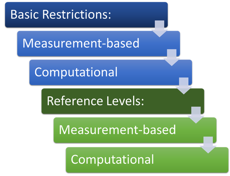
5.5.2. Basic restrictions
This section specifies requirements related to assessments based on the basic restrictions. These assessments are generally preferred, particularly when the exposure region is within the reactive near-field region of the transmitting antenna(s), which is often the case below 10 MHz. It is permissible to assess against the reference levels when an assessment against the basic restrictions is not feasible or practical. In these situations, the reference levels become levels that shall not be exceeded.
5.5.2.1. General requirements
For a given EUT, RF exposure condition, and corresponding separation distance, the SAR and internal E-field levels induced within the body shall not exceed the applicable basic restrictions.
5.5.2.2. Measurement-based assessments
The preferred assessment method is measurement of the induced SAR and internal E-field within a representative tissue-equivalent phantom at the corresponding separation distance. However, this may not always be feasible due to physical constraints, or the availability of suitable test equipment, tissue-equivalent phantom definitions and/or conservative assessment procedures.
The requirements for measurement-based assessments against the basic restrictions can be found in section 6.
5.5.2.3. Computational assessments
When the practical limitations of the test equipment or tissue-equivalent phantom prohibit a measurement-based assessment, a computational assessment against the basic restrictions may be performed.
Computational assessment methods are described in section 8.
5.5.3. Reference levels
This section specifies requirements related to assessments based on the reference levels. Reference levels provide a means of assessing exposure based on incident field strengths instead of induced quantities. Many of the practical constraints associated with assessments against the basic restrictions are removed: the E- and H-fields produced by the EUT are evaluated in free space at the corresponding separation distance.
5.5.3.1. General requirements
For a given EUT, RF exposure condition, and corresponding separation distance, the NS- and SAR-based reference levels should not be exceeded. When the NS- and SAR-based reference levels are exceeded, an assessment against the basic restrictions shall be performed for the EUT.
5.5.3.2. Measurement-based assessments
Provided that suitable field probes and test equipment are available, the preferred method when assessing against the reference levels is measurement of the incident field strengths.
The requirements for measurement-based assessments against the reference levels can be found in section 7.
5.5.3.3. Computational assessments
When incident field measurements are not feasible, either due to physical constraints or the availability of suitable field probes and test equipment, the field levels may instead be evaluated computationally.
Computational assessment methods are described in section 8.
5.5.3.4. Special considerations for whole-body exposure
The reference levels specified in RSS-102 are based on incident fields that are uniform over the volume of the human body. In the context of RF exposure from an EUT, whole-body exposure may occur for certain combinations of separation distance and source antenna dimensions, e.g. when one or both are comparable to, or larger than, the human body. Although it is assumed that the whole body is being exposed, the incident fields may not be spatially uniform, and comparing the spatial maxima to the corresponding reference levels may be overly conservative.
Spatial averaging may be applied for whole-body exposure assessments against the reference levels in accordance with annex B, provided the following conditions are met:
- an assessment against the basic restrictions is not feasible
- when performing a measurement-based assessment, the field levels are consistently and measurably within the sensitivity range of the employed field probe at all spatial averaging locations and frequencies (probe sensitivity requirements are presented in section 7.1.6.1)
- the maximum exposure ratio observed over all spatial averaging locations is not greater than twice the spatially averaged exposure ratio (procedures for evaluating exposure ratios in measurement-based assessments against the reference levels are presented in section 7.2)
- the rationale and procedure are properly documented in the RF exposure technical brief
5.5.3.5. Special considerations for localized exposure
Localized exposure may also occur, e.g. when the separation distance and dimensions of the source antenna are small relative to the human body. Alternatively, the fields produced by the EUT may be largely confined to an area that is inaccessible to the entire body. In cases where the exposure occurs primarily within the limbs, comparing the highest observed field strength to the reference level may be overly conservative. This is particularly true for the H-field reference levels, as the conversion from incident H-field to internal E-field depends upon the size of the exposed region.
The relaxed H-field reference levels provided in table 2 may be applied for localized exposure assessments, provided the following conditions are met:
- an assessment against the basic restrictions is not feasible
- no spatial averaging is applied
- the rationale and procedure are properly documented in the RF exposure technical brief
When employing the relaxed H-field reference levels for limb exposure, compliance shall also be demonstrated at the head/torso position without relaxation, i.e. a relaxation factor of 1.0 in accordance with table 2. Refer to annex E for examples involving various device types.
| Exposure region | Relaxation factor | NS-based H-field (A/m RMS) |
|---|---|---|
| Head/torso | 1.0 | 90 |
| Leg | 1.5 | 135 |
| Arm | 2.5 | 225 |
| Hand/foot | 5.0 | 450 |
6. Measurement-based assessments against the basic restrictions
This section provides the requirements related to measurement-based assessments against the basic restrictions for SAR and internal E-field in the frequency range of 3 kHz to 10 MHz.
6.1. SAR
SAR levels induced by emissions in the range of 4 MHz to 6 GHz shall be measured in accordance with RSS-102.
6.2. Internal E-field
ISED will provide the requirements for measurement-based assessments against the basic restriction for internal E-field in a future issue of SPR-002.
Until these requirements are available, applicants wishing to perform a measurement-based assessment against the basic restriction for internal E-field shall submit an inquiry to ISED proposing an accurate and conservative approach for doing so.
7. Measurement-based assessments against the reference levels
This section provides the requirements related to measurement-based assessments against the reference levels in the frequency range of 3 kHz to 10 MHz.
7.1. Test set-up
This section specifies the requirements for the test set-up.
7.1.1. Overview
Figure 2 illustrates a typical test set-up for performing incident-field measurements. The field probe used to conduct the measurements primarily consists of one or more probe antennas and a measurement receiver. Fields generated by the EUT excite a response in the probe antenna(s), which is processed by the measurement receiver and converted to an estimate of the desired exposure metric. In many cases, the probe antenna(s) and measurement receiver are integrated into a single device, and may share the same enclosure. Alternatively, a measurement receiver may be used with a variety of detachable probe antennas. Regardless, the measurement receiver shall present a suitable impedance to each antenna, and be capable of accurately converting the detected quantity (i.e. voltage or current) to the measured field strength (i.e. E-field or H-field) over the full frequency range of the assessment.
Figure 2: Illustration of a typical incident-field measurement
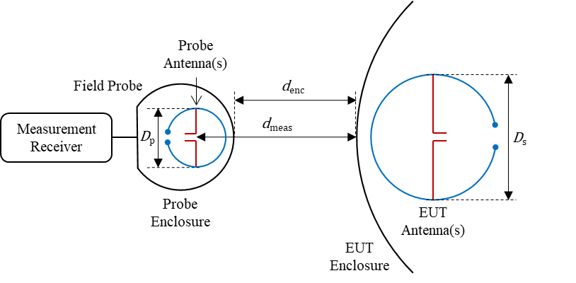
The distance corresponding to a given field measurement, denoted by \(d_{meas}\) in figure 2, is defined as the distance separating the EUT enclosure and the measurement location associated with the probe antenna(s), i.e. the precise location in space that corresponds to the field measurement. If this location is not indicated by the probe manufacturer, the geometric centre of the probe antenna(s) or the probe enclosure may be used.
The enclosure distance, denoted by \(d_{enc}\) in figure 2, is the distance between the EUT and the nearest surface of the field probe enclosure.
In contrast, the separation distance, \(d_{sep}\), is the minimum distance between the EUT and the nearest surface of the exposure region, i.e. the region over which RF exposure is to be evaluated. It is based on the RF exposure condition and limit under consideration. Limits to prevent NS are based on instantaneous exposure, while those preventing thermal effects are based on average exposure over any six-minute period. Consequently, the NS- and SAR-based separation distances may be different. For example, if the user interacts directly with the EUT (e.g. portable devices or wireless chargers), an assessment against the NS-based limits shall be conducted at touch position, i.e. \(d_{sep}=0\) mm, regardless of whether the EUT might be considered as a table-top device or not.
Ideally, incident field measurements would be performed at the corresponding separation distance, i.e. \(d_{meas} = d_{sep}\). However, this may not be feasible in all cases due to spatial averaging effects (see section 7.1.7) and physical constraints. In such cases, a computational assessment as per section 8 may be performed. Alternatively, curve-fitting techniques may be used to estimate the field value(s) at dsep based on measurements taken at larger distances, provided an acceptable estimation error can be demonstrated, which requires submitting an inquiry to ISED.
The shortest distance separating the probe and EUT antennas, denoted by \(d_{meas}\) in figure 2, is proportional to the probe antenna size requirements outlined in section 7.1.7.
7.1.2. Environment
When feasible, the assessment shall be performed in a controlled laboratory environment. The test set-up shall be kept well clear of metal objects or surfaces that can influence the assessment results. Tables and mounting apparatus for the measurement probes shall be RF transparent and their construction shall be free of metallic materials. The volume and shape of the electromagnetic field (as influenced by EUT output power and radiator size) shall be taken into consideration using best engineering practices to determine the appropriate clearance required to minimize the influence of metallic materials in the vicinity of the EUT.
In addition, the environment should be free of ambient signals within the frequency and sensitivity ranges of the field probe(s). If necessary, these signals may be measured and removed from the results, provided this is clearly documented in the RF exposure technical brief.
If the nature of the EUT is such that laboratory measurements are not feasible or practical, e.g. for an electronic article surveillance system, the assessment shall be performed in situ on at least three representative installations.
7.1.3. Reported quantities
In the RF exposure technical brief, E-field values shall be reported in V/m, while H-field values shall be reported in A/m.
Note: For free space and other nonmagnetic media such as air, the magnetic field strength (H) is related to the magnetic flux density (B) by the permeability of free space ( \(\mu_{0}\) ) as follows:
(1)
7.1.4. Frequency-domain vs. time-domain assessments
Measurement receivers can operate primarily in the frequency domain (e.g. spectrum analysis) or the time-domain (e.g. an oscilloscope). Frequency-domain assessments are less complex, particularly for SAR because the reference levels are frequency-dependent; however, frequency-domain assessments are not always appropriate.
If the EUT emissions consist of unmodulated carriers (periodic sinewaves, pulse trains, etc.), a frequency-domain assessment may be performed. This may be extended to emissions consisting of narrowband-modulated carriers, provided the resolution bandwidth (RBW) employed at each measurement frequency exceeds the occupied bandwidth (OBW) of the emission at that frequency. In the context of SPR-002, modulation is classified as narrowband if the OBW is less than 1% of the carrier frequency. At a given frequency, measurement receivers operating primarily in the frequency domain shall employ an RBW in the range of 1% to 10% of the carrier frequency. In addition, they shall be capable of performing statistical functions such as mean and max-hold at each frequency, and shall be configured to use a peak detector to display RMS equivalent levels.
For all other EUT emissions (e.g. aperiodic or broadband-modulated), a time-domain assessment shall be performed. Measurement receivers operating primarily in the time-domain shall sample the field measurement signal(s) at a rate that is sufficiently high to prevent aliasing and fold-over effects, i.e. the sampling frequency or frequencies shall be higher than twice the highest frequency associated with the assessment.
7.1.5. Assessment frequency range
The assessment shall consider the full frequency range of the corresponding exposure limit:
- 3 kHz to 10 MHz for the NS-based E- and H-field reference levels
- 100 kHz to 10 MHz for the SAR-based H-field reference level
- 1.10-10 MHz or 1.29-10 MHz for the SAR-based E-field reference level in uncontrolled or controlled environments, respectively
For EUT emissions meeting the requirements for a frequency-domain assessment outlined in section 7.1.4, multiple equipment set-ups may be employed to cover the full frequency range of a given exposure limit. This shall be noted in the RF exposure technical brief.
A reduced frequency range may be permitted for a given assessment, provided the EUT does not produce:
- frequency components with emissions that are less than 20 dB below the maximum level identified over the frequency range of 3 kHz to 10 MHz; or
- emissions exceeding the probe sensitivity levels specified in 7.1.6.1 outside of this range.
This shall be demonstrated via preliminary measurements using either a spectrum analyzer or a measurement receiver with a field probe that accommodates the full frequency range of the exposure limit under consideration and meets the requirements outlined in sections 7.1.6.1, 7.1.6.2, 7.1.6.3 and 7.1.7.2. The resulting spectrum plot(s) shall be included in the RF exposure technical brief.
7.1.6. Probe requirements
This section specifies the applicable requirements for the probe.
Calibration data from an accredited calibration laboratory for the following subsections shall be provided in the RF exposure technical brief.
7.1.6.1. Probe sensitivity
The field probe(s) shall meet the following sensitivity requirements over the frequency range of the assessment:
- ≤ 1 V/m for E-field measurements
- ≤ 1 A/m for H-field measurements against the NS-based reference level
- ≤ 0.1/ fMHz A/m for H-field measurements against the SAR-based reference level, where fMHz is the measurement frequency in MHz
7.1.6.2. Probe level response
The field probe shall provide for an amplitude flatness of 1 dB or less over the entire frequency range of the assessment. Frequency-dependant amplitude weighting factors shall not be applied to the measurement results.
7.1.6.3. Probe linear range and linearity error
The field probe shall provide for a linear range extending from at least -10 dB to +5 dB relative to the reference level associated with the assessment, and with a linearity error within ±0.5 dB.
7.1.7. Probe antenna requirements
This section specifies the applicable requirements for the antenna inside the field probe.
Most RF exposure assessments below 10 MHz are performed in the reactive near-field region of the EUT antenna(s). Spatial variations in the magnitude and polarization of the E- and H-fields can be significant in this region, and, as a result, care must be taken when selecting a suitable probe antenna. In addition to the requirements outlined in the following subsections, field probes used to perform assessments within the reactive near-field region shall employ antennas that are designed and intended for near-field measurements.
7.1.7.1. Antenna size
Due to the finite size of the probe antenna(s), all field measurements will be subject to some degree of spatial averaging. For a loop antenna, the measurement location may be defined as the geometric centre of the loop, but the result will be a function of the average H-field passing through the loop aperture. A similar E-field averaging effect occurs in wire antennas.
The probe antenna shall be sufficiently small to ensure that the spatial peak of a given field component can be accurately measured. Referring to quantities illustrated in figure 2 above, the following condition shall be maintained to ensure this:
(2)
If the maximum linear dimension of the probe antenna (Dp) is unknown, the maximum enclosure dimension shall be used. This requirement may be waived if one of following conditions is met:
- Dp≤ 0.1Ds, where Ds is the maximum linear dimension of the largest active EUT antenna (the maximum dimension of the EUT enclosure shall not be used)
- the nearest metallic surface (excluding the source antenna and accompanying electronics) is further than 1.7Dp from the field measurement point, e.g. geometric centre of the probe antenna(s)
Example: The smallest antenna of a given EUT has a maximum dimension of 40 mm. This would correspond to the length of a dipole antenna, or the diameter of a circular loop antenna. The maximum dimension of the probe antenna is 12 mm. As a result, incident field measurements may only be performed at distances of at least 20 mm (dmeas≥20 mm).
7.1.7.2. Isotropy
The reference levels are defined in terms of the vector magnitude of the incident field. Consequently, field measurements shall be performed for three orthogonal axes, defined as x, y and z for convenience, to enable calculation of the vector magnitude.
For EUT emissions requiring a time-domain assessment in accordance with section 7.1.4, the x, y and z components are recommended to be detected simultaneously by the measurement receiver. This should be achieved using a three-axis isotropic probe with a deviation from isotropy of 1 dB or less.
When performing measurements within the reactive near-field region, the individual elements of a three-axis probe antenna should share the same measurement centres (e.g. a three-axis H-field probe consisting of three concentric loops). If the maximum distance separating the measurement locations of any two elements exceeds Dp/20, where Dp is the maximum dimension of the probe antenna, the probe antenna shall not be considered “isotropic” in the reactive near-field region.
For EUT emissions meeting the requirements for a frequency-domain assessment in accordance with section 7.1.4, each field component may be measured sequentially, provided the corresponding antenna positioning requirements in section 7.1.7.3 are met.
7.1.7.3. Antenna positioning
The positioning apparatus for the field probe shall enable movement and orientation of the probe antenna(s) such that the maximum field levels produced by the EUT can be accurately and repeatably measured at the corresponding separation distance (assuming this is feasible based on the sized of the probe antennas). This requires aligning the measurement centre(s) of the probe antenna(s) with the location(s) of maximum exposure on the evaluation surface. The measurement set-up and positioning apparatus shall enable scanning of the measurement centre(s) of the probe antenna(s) on the evaluation surface, in any direction relative to the geometric centre of the EUT, without obstruction.
Example: When evaluating a table-top device, the probe antenna enclosure should not rest on, or be obstructed by, the table or surface upon which the EUT rests, or any other surface at the same height, as this can unduly prohibit vertical scanning of the measurement centre(s) of the probe antenna(s) at or below the height of the geometric centre of the EUT.
When performing sequential measurements of the x, y and z field components to determine the vector magnitude of the field in a frequency-domain assessment (see section 7.1.7.2), the positioning apparatus shall enable rotation of the probe antenna such that each field component can be accurately and repeatably measured at the same location on the evaluation surface. The results obtained via sequential measurements shall be equivalent to those obtained using a three-axis isotropic probe antenna with a deviation from isotropy of 1 dB or less. If the measurements are performed within the reactive near-field region, the positioning apparatus shall be capable of repeatably orienting the probe antenna(s) such that the maximum distance between any two field component measurements does not exceed Dp/20.
7.2. Measurement procedure
This section specifies the requirements related to the measurement procedure.
7.2.1. General requirements related to the measurement procedure
Measurements shall be performed in accordance with the following the requirements for both the E- and H-field levels; calculations to derive one from the other will not be accepted.
For a given exposure condition, the user-accessible space surrounding the EUT shall be considered at the corresponding separation distance. Whenever possible, all transmitters capable of simultaneous operation shall be active throughout the assessment. Otherwise, the exposure contributions of each transmitter, or a combination thereof, shall be evaluated and combined in accordance with section 9. Photographs depicting the full test set-up, particularly for the configurations yielding highest exposure, shall be provided.
Preliminary scanning measurements should be performed to determine the location(s) of maximum exposure (i.e. where the E- and H-field levels are highest) on the evaluation surfaces associated with each user-accessible side of the EUT. At least one worst-case E- and H-field measurement shall be performed for each user-accessible side of the EUT.
If the EUT employs fundamental, carrier or pulse repetition frequencies that can vary over time, the assessment shall capture the worst-case exposure arising from all possible combinations of frequency and excitation level.
7.2.2. Frequency-domain assessment
This section applies to frequency-domain assessments.
7.2.2.1. General requirements for frequency-domain assessments
In accordance with section 7.1.4, the assessment may be performed in the frequency-domain if the transmit waveforms consist of unmodulated or narrowband-modulated periodic carriers. It is assumed that the measurement receiver computes and/or displays the RMS equivalent level (using a peak detector) associated with each frequency component; otherwise, the values shall be scaled appropriately.
The vector magnitude of the RMS E-field level, denoted by E(f), can be expressed as:
(3)
where \( E_{x}(f) \), \( E_{y}(f) \) and \( E_{z}(f) \) are the x, y and z components of the RMS equivalent E-field level (using a peak detector), respectively. Similarly, for the H-field:
(4)
Note: As these are the RMS levels of a largely periodic signal, the components need not be measured simultaneously, i.e. single-axis measurements may be performed.
At a given frequency, the RBW of the measurement receiver shall be in the range of 1% to 10% of that carrier frequency.
7.2.2.2. NS-based reference levels
The NS-based reference levels apply to the maximum instantaneous RMS E- and H-fields, respectively. When performing an assessment in the frequency domain, the maximum instantaneous RMS value can be conservatively evaluated by summing the maximum RMS levels associated with each frequency component of the EUT emission. For this, the measurement receiver shall record/display the spectrum in a max-hold configuration. The measurement time interval shall allow for the spectrum levels to converge, and shall not be less than 1 second.
Once the spectrum levels have converged, the RMS contributions can be combined. To limit the effects of measurement noise on the assessment results, the frequency components considered in the summation may be limited to those for which the field levels exceed the corresponding sensitivity levels specified in section 7.1.6.1. Thus, the NS-based exposure ratio associated with the incident E-field, denoted as \( ER_{NS-ERL} \), can be computed as:
(5)
where:
- M is the total number of frequency components for which the field levels are within the probe sensitivity range
- fm is the frequency of the m-th component
- ENS-RL is the NS-based reference level for the incident E-field
Similarly, for the H-field:
(6)
7.2.2.3. SAR-based reference levels
The SAR-based reference levels apply to the maximum time-averaged RMS E- and H-fields observed over any six-minute period. Consequently, the impact of a six-minute rolling time-average shall be considered in the assessment. This may be achieved by applying the time-averaging operation to each frequency component and capturing the worst-case SAR-based exposure ratio, or, with sufficient rationale, via calculated scaling factors based on the nature of the transmit waveforms.
Let \( E_{avg}(f) \) and \( H_{avg}(f) \) denote the maximum time-averaged RMS E- and H-field levels associated with each frequency component, respectively. As in section 7.2.2.2, the frequency components considered in the assessment may be limited to those for which the field levels exceed the corresponding sensitivity levels specified in section 7.1.6.1.
When computing the SAR-based exposure ratio, E- and H-field contributions occurring at the same frequency need not be added together; only the highest contributor is considered. Consequently, the SAR-based exposure ratio, denoted by \( ER_{SAR-RL} \), can be expressed as:
(7)
where:
- M is the total number of frequency components the field levels are within the probe sensitivity range
- fm is the frequency of the m-th component
- HSAR-RL and ESAR-RL are the SAR-based reference levels for the incident E- and H-fields, respectively
- fmin,E is the minimum frequency for which ESAR-RL is defined (see section 7.1.5)
7.2.3. Time-domain assessment
This section applies to time-domain assessments.
7.2.3.1. General requirements for time-domain assessments
When a time-domain assessment is performed, the x, y and z components of the E- and H-fields shall be measured simultaneously. The measurement receiver shall directly sample the associated RF signals, with all subsequent processing and detection steps being performed computationally. In other words, the measurement receiver shall output and/or display the instantaneous field values instead of the envelope or the RMS level(s) associated with a given frequency component. The vector magnitude of the instantaneous E-field, denoted by E(t), can be expressed as:
(8)
where Ex(t), Ey(t) and Ez(t) are the x, y and z components of the instantaneous E-field, respectively. Similarly, for the H-field:
(9)
7.2.3.2. NS-based reference levels
The NS-based reference levels apply to the maximum instantaneous RMS E- and H-fields, respectively. For convenience, the analytical steps will be demonstrated for the E-field. The same steps shall be applied to the H-field.
The instantaneous RMS E-field, Erms(t) can be expressed as:
(10)
where T corresponds to the inverse of the highest frequency associated with the assessment and \( \tau \) represents the time variable in the integrand (it is only introduced to avoid ambiguity in the equation).
Note A conservative value of T=0.1 μs may be used, or Erms (t) may be set equal to E(t).
The maximum instantaneous RMS value of the E-field, Emax, shall be the maximum value of Erms (t) observed over the full measurement time interval, which, in turn, shall be sufficiently long to ensure that Emax has converged. This time interval shall not be less than 1 second.
Based on the value of Emax and the corresponding reference level, ENS-RL, the exposure ratio contribution associated with this measurement can be computed as:
(11)
where ERNS-ERL is the NS-based exposure ratio contribution from the incident E-field. Similarly, for the H-field we have:
(12)
7.2.3.3. SAR-based reference levels
Additional care must be taken when performing a time-domain assessment against the SAR-based reference levels, as they apply to the maximum time-averaged RMS E- and H-fields observed over any six-minute period, and they are frequency dependent. An approach to achieve this is presented in annex C; however, in some cases, other solutions may be more practical. To propose an alternative approach that is equally or more conservative, an inquiry shall be submitted to ISED.
8. Computational assessments
This section provides the requirements that are specific to computational assessments, whether they be performed against the basic restrictions or reference levels.
8.1. Computational tool and method
The computational tool shall be clearly identified in the RF exposure technical brief. It should employ one of the following full-wave computational methods:
- finite-difference time-domain (FDTD) / finite integration technique (FIT)
- finite element method (FEM)
Otherwise, an inquiry shall be submitted to ISED, which describes the proposed method and how it can be used to perform a conservative RF exposure assessment.
8.2. Code verification
The selected tool shall be demonstrated to meet the code verification requirements outlined in the international standard that most closely aligns with the chosen technique (e.g. IEC/IEEE 62704-1 for FDTD/FIT or IEC/IEEE 62704-4 for FEM).
8.3. Computational model
This section provides the requirements related to the computational model.
8.3.1. EUT model
The procedure for modelling the EUT shall be described in the RF exposure technical brief. Relevant mechanical dimensions and material properties shall be provided, along with the associated tolerances.
It is often necessary to simplify, omit or substitute certain aspects of the EUT model to reduce simulation times and accommodate memory limitations. A description of these modifications, and the expected impact on the assessment results, shall be provided in the RF exposure technical brief.
8.3.2. EUT excitation and loading
The excitation(s) applied to the EUT model must match the corresponding transmit waveforms as closely as possible. If these consist of unmodulated or narrowband modulated carriers, i.e. the requirements for a frequency-domain assessment outlined in section 7.1.4 are met, the spectrum of the simulated emissions shall include all frequency components for which the field levels exceed the corresponding sensitivity levels specified in section 7.1.6.1. These shall be identified through preliminary measurements, using a field probe that meets the requirements outlined in sections 7.1.5, 7.1.6.1, 7.1.6.2, 7.1.6.3 and 7.1.7.2. Relative agreement between the levels of simulated and measured frequency components shall be demonstrated in the RF exposure technical brief.
This may be done either by showing:
- plots demonstrating good correlation between the simulated and measured values or
- the deviation between the simulated and measured values are within the combined uncertainty using equations 15 and 8 of IEC/IEEE 62704-1 and IEC/IEEE 62704-4, respectively
If the EUT includes components that are loaded (e.g. a WPT client or an RFID tag), the impact of loading on the emission spectra shall be modelled as closely as possible to ensure that the computational model is able to capture the worst-case exposure ratio(s).
It should be noted that additional requirements related to WPT implementations are provided in annex D.
For aperiodic or broadband-modulated EUT emissions, an inquiry proposing a conservative excitation and/or load modelling approach shall be submitted to ISED.
8.3.3. Simulation parameters and computational resources
All relevant simulation parameters, such as those related to the meshing, boundary conditions, convergence, etc., as well as the computational resources required to reproduce the simulation results, shall be provided in the RF exposure technical brief.
8.3.4. Phantom properties
For assessments against the basic restrictions, it is necessary to model a tissue-equivalent phantom within which the induced SAR and/or internal E-field can be evaluated. At the time of this writing, a general and internationally accepted approach for modelling the interaction between human tissue and RF fields below 10 MHz is not yet available.
When assessing local exposure in the body, torso or limbs, the flat elliptical phantom defined in IEC/IEEE 62209-1528, with the material properties summarized in table 3, may be used. The dimensions of the phantom may be reduced, provided that there is no measurable effect on the assessment results. This shall be demonstrated in the RF exposure technical brief.
Otherwise, a detailed inquiry proposing a conservative phantom definition shall be submitted to ISED for approval.
| Property | Symbol | Value |
|---|---|---|
| Dielectric constant | \( \varepsilon _{r} \) | 55 (-) |
| Electrical conductivity | \(\sigma\) | 0.75 S/m |
| Mass density | \(\rho\) | 1000 kg/m3 |
Note: The material properties in table 3 stem from IEC/IEEE 62209-1528. Although the requirements in IEC/IEEE 62209-1528 are limited to ≥ 4 MHz, the material properties summarized in table 3 may be used below 4 MHz for the purposes of SPR-002.
8.3.5. Uncertainty
This section provides the requirements related to computational uncertainty analysis.
8.3.5.1. General requirements related to computation uncertainty analysis
A complete uncertainty analysis shall be conducted and presented in accordance with the international standard that most closely aligns with the chosen computational method (e.g. IEC/IEEE 62704-1 for FDTD/FIT or IEC/IEEE 62704-4 for FEM). The uncertainty budget, which shall be provided in the RF exposure technical brief, should demonstrate that the expanded (k = 2) uncertainty of the computational model is ≤30%. Otherwise, an inquiry shall be submitted to ISED.
The steps taken in evaluating each component of the uncertainty budget shall be provided in the RF exposure technical brief.
8.3.5.2. Simulation uncertainty
Deviations from the prescribed procedures for evaluating the various simulation uncertainties may be necessary, as international standards such as IEC/IEEE 62704-1/-4 were not developed for the frequency range covered here. For example:
- Mesh resolution (FDTD / FIT): If the requirements provided in section 7.2.3 of IEC/IEEE 62704-1 are too computationally burdensome, this uncertainty may instead be evaluated by increasing the total number of mesh cells by a factor of 2 or, when applying sub-gridding, by a factor of 4 in the region of highest exposure (including the source antenna(s)).
- Boundary conditions (FDTD / FIT / FEM): If the requirements provided in section 7.2.4 of IEC/IEEE 62704-1 or section 7.2.3 of IEC/IEEE 62704-4 are too computationally burdensome, this uncertainty may instead be evaluated by increasing the size of the bounding box by 50% in all directions.
- Convergence (FDTD / FIT): If the requirements provided in section 7.2.6 of IEC/IEEE 62704-1 are too computationally burdensome, the following may be applied: the simulation time required for convergence, Tconv, shall be long enough to ensure that the maximum RMS field level remains in the same voxel when the simulation time is increased to 1.5 Tconv, i.e. that the location of the maximum RMS field level does not change. In addition, the field level associated with this voxel shall not change by more than 2%. Either the E- or H-field may be considered, whichever is dominant in the context of exposure. The percent change in the maximum RMS field level when increasing from Tconv to 1.5 Tconv shall be taken as the convergence uncertainty, with a rectangular distribution.
- Phantom dielectrics (FDTD / FIT / FEM): When using the flat and homogeneous phantom with the material properties summarized in table 3 above, this uncertainty may be set to zero.
For all other deviations, an inquiry shall be submitted to ISED.
8.3.5.3. EUT model uncertainty and validation
A complete uncertainty analysis involves performing measurements to validate the EUT model and determine its uncertainty. For emissions above 4 MHz, this shall be performed in accordance with section 7.3 in IEC/IEEE 62704-1 (FDTD/FIT) or IEC/IEEE 62704-4 (FEM), with IEC/IEEE 62209-1528 serving as a reference for SAR measurements. This extends to emissions below 4 MHz, with the exception of section 7.3.3 in IEC/IEEE 62704-1/-4, which prescribes SAR measurements for validation. While these requirements form the basis for the approach, modifications may be necessary for practical reasons. The following requirements may be applied in lieu of section 7.3.3 in IEC/IEEE 62704-1/-4:
- Instead of SAR measurements, incident field measurements may be performed throughout the exposure region. This may be limited to either the E- or H-field, if it is demonstrated that the other field does not contribute to the resulting exposure ratio.
- Where possible, the worst-case exposure scenario and separation distance(s) shall be considered.
- Field probes used to perform the measurements shall meet the requirements outlined in sections 7.1.5, 7.1.6.1, 7.1.6.2 and 7.1.6.3 of this document. They should also meet the requirements outlined in section 7.1.7, otherwise, the effects of spatial averaging and anisotropy shall be incorporated into the validation, either by post-processing the simulated field results or including the probe antenna(s) in the computational model for validation.
- When defining the points in space at which measurements will be compared with simulation results, the following considerations apply:
- Measurements shall be performed at no fewer than 25 points. If possible, these shall be distributed over at least two surfaces, with one being at the separation distance, i.e. on the evaluation surface or nearest surface of the exposure region.
- If possible, one of the measurement points shall capture the maximum field level within the exposure region.
- The distance between neighbouring measurement points shall not exceed 100 mm, and should be small enough that the difference in neighbouring field levels is less than 6 dB.
- If possible, the spatial distribution of the measurement points shall be such that a good spread of field levels within 20 dB of the maximum field level is obtained.
- With regard to the uncertainty budget:
- The uncertainty of the EUT model may be calculated in accordance with section 7.3.3 in IEC/IEEE 62704-1/-4, but with squared field values, e.g. |E|2 or |H|2, being used in place of SAR values.
- The uncertainty of the flat phantom model is zero. If other phantoms are used, a detailed inquiry proposing conservative phantom uncertainty shall be submitted to ISED for approval.
- The uncertainty of the measurement equipment and procedure shall be estimated as closely as possible based on information provided by the test equipment manufacturer, field probe positioning, etc.
- The procedure in section 7.3.4 of IEC/IEEE 62704-1 (FDTD/FIT) or section 7.3.5 of IEC/IEEE 62704-4 (FEM) shall be followed to demonstrate that the EUT model is valid.
If measurements within the exposure region are prohibited by physical constraints, minor modifications may be applied to the EUT to allow access, provided that they do not have a significant impact on the assessment results. For example, non-conductive enclosure materials may be displaced or removed if it is demonstrated, via simulation or otherwise, that they do not significantly impact the field distribution within the exposure region. Alternatively, individual portions of the EUT may be modelled and validated independently, if it is demonstrated that the overall fields produced by the EUT are equivalent to the superposition of the fields produced by each portion in isolation. If neither option is viable, an inquiry shall be submitted to ISED.
A detailed description of the EUT model validation procedure shall be provided in the RF exposure technical brief, along with model validation results and plots or tables demonstrating agreement between measured and simulated results.
8.4. Exposure assessments
Once the computational model has been validated, exposure assessments can be performed. This section provides the requirements in this regard.
8.4.1. Number of assessments
Assessments shall be performed for each exposure scenario and separation distance identified in sections 5.1 and 5.2, respectively, unless sufficient rationale is provided for a reduced set of worst-case exposure scenarios and separation distances in the RF exposure technical brief.
8.4.2. Assessments against the basic restrictions
This section provides the requirements for computational assessments against the basic restrictions.
8.4.2.1. Phantom
When performing an exposure assessment against the basic restrictions, a tissue-equivalent phantom shall be added to the computational model at the corresponding separation distance, and oriented to yield worst-case exposure.
For the flat phantom defined in section 8.3.4, one of the larger surfaces shall face the EUT such that it captures the highest incident fields. Care should be taken to ensure that the edges and corners of the phantom are not placed in high-field regions, as the induced quantities may become artificially high in these areas.
8.4.2.2. SAR
The 1-g or 10-g averaged SAR shall be evaluated within the phantom in accordance with the relevant international standard (e.g. IEC/IEEE 62704-1 for FDTD/FIT or IEC/IEEE 62704-4 for FEM). The transmit duty cycle(s) employed by the EUT may be incorporated into the assessment, provided the maximum six-minute-averaged result is captured.
Assuming the associated EUT emissions meet the conditions for a frequency-domain assessment, the SAR-based exposure ratio, \(ER_{SAR-BR}\), can be calculated as follows:
(13)
where:
- SARBR is the applicable basic restriction for SAR (e.g. 1.6 W/kg averaged in 1-g for head, neck and trunk, 4 W/kg averaged in 10-g for limbs)
- N is the number of frequency components associated with the SAR assessment
- SAR(fn) is the SAR contribution of the n-th frequency component
One or more plots illustrating the SAR or \(ER_{SAR-BR}\) distribution throughout the phantom shall be included in the RF exposure technical brief, and the maximum value should be clearly indicated. The maximum \(ER_{SAR-BR}\) result shall be reported.
8.4.2.3. Internal E-field
Using the same meshing approach as is used for SAR, i.e. in accordance with IEC/IEEE 62704-1 for FDTD/FIT or IEC/IEEE 62704-4 for FEM, but without performing any spatial averaging, the spatial peak RMS E-field strength within the phantom shall be identified. The transmit duty cycle(s) employed by the EUT shall not be incorporated into the assessment, as the NS limits are based on instantaneous exposure.
Assuming the associated EUT emissions meet the conditions for a frequency-domain assessment, the NS-based exposure ratio, \(ER_{NS-BR}\), can be calculated as follows:
(14)
where:
- M is the number of frequency components associated with the internal E-field assessment
- \(E_{int} (f_{m})\) is the internal E-field contribution of the m-th frequency component
- \(E_{BR} (f_{m})\) is the appliable basic restriction for the internal E-field of the m-th frequency component
Particular care should be taken when evaluating the spatial peak (maximum internal E-field), as this value may be subject to discretization uncertainties. It is necessary to determine if the spatial peak obtained is sufficiently converged. This may be evaluated by additional simulations with refined mesh resolution at the location of the spatial peak. In situations where the spatial peak is sufficiently converged, an increase of the mesh resolution by a factor of 2, should lead to a negligible difference between the original and the new simulation. Where the spatial peak is not sufficiently converged, there will be a large deviation between the spatial peaks recorded for both simulations.
The plots demonstrating the E-field distribution within the phantom shall be provided, and the maximum internal E-field result should be clearly identified. The maximum ERNS-BR result shall be reported.
It is important to note when evaluating internal E-field, the duty cycle(s) employed by the WPT source(s) shall not be incorporated, as the corresponding basic restrictions are for instantaneous exposure.
8.4.3. Assessments against reference levels
When neither an assessment against the basic restrictions nor a measurement-based assessment against the reference levels is feasible, a computational assessment against the reference levels shall be performed. This section provides the requirements in this regard, provided that the emissions consist of unmodulated or narrowband modulated carriers, i.e. they meet the requirements for a frequency-domain assessment outlined in section 7.1.4. Otherwise, an inquiry shall be submitted to ISED in accordance with section 8.3.2.
Based on the relevant requirements provided in section 7.2, excluding 7.2.3, the values of \(ER_{NS-ERL}\), \(ER_{NS-HRL}\) and \(ER_{SAR-RL}\) shall be computed on the evaluation surface (i.e. at the corresponding separation distance) for each user-accessible side of the EUT.
In addition, plots of the RMS E- and H-fields on each evaluation surface shall be provided. The maximum RMS field level should be clearly indicated on each plot. When the excitation and loading produce multiple frequency components to be included in the assessment, the following procedures shall be followed:
- if a fixed fundamental, carrier or pulse repetition frequency is employed, provide plots for this frequency and a table summarizing the maximum RMS field levels on the evaluation surface for each frequency component included in the assessment
- if a variable fundamental, carrier or pulse repetition frequency is employed, follow the requirements in (i) for the frequency yielding the worst-case exposure
- if multiple fundamental, carrier or pulse repetition frequencies are employed simultaneously, follow the requirements in (i) for each of these frequencies
9. Total exposure
Compliance with the limits to prevent NS and thermal effects is demonstrated if the worst-case total exposure ratios (TERs) corresponding to each effect are less than or equal to 1. These TERs are evaluated separately, based on the corresponding NS- or SAR-based exposure ratios and in accordance with the following sections.
9.1. NS-based total exposure ratio
The frequency range associated with the NS-based limits matches that of SPR-002. As a result, the NS-based TER, denoted by \(TER_{NS}\) can be evaluated based on the NS-based exposure ratios obtained in sections 6, 7 and/or 8 as follows:
(15)
where:
- N is the number of simultaneously operating transmitters for which an assessment against the basic restriction for internal E-field may have been performed
- \(ER_{NS-BR,n}\) is the NS-based exposure ratio of the n-th simultaneously operating transmitter for which an assessment against the basic restriction for internal E-field may have been performed
- M is the number of simultaneously operating transmitters for which an assessment against the NS-based reference levels may have been performed
- \(ER_{NS-ERL,m}\) is the NS-based exposure ratio of the m-th simultaneously operating transmitter for which an assessment against the NS-based reference level for incident E-field may have been performed
- \(ER_{NS-HRL,m}\) is the NS-based exposure ratio of the m-th simultaneously operating transmitter for which an assessment against the NS-based reference level for incident H-field may have been performed
The maximum TERNS values shall be provided in the RF exposure technical brief for each exposure condition, and the highest value shall be clearly indicated. Compliance with the NS-based limits is demonstrated if the worst-case TERNS≤1.
9.2. SAR-based total exposure ratio (100 kHz to 10 MHz)
SAR-based exposure ratios obtained in accordance with sections 6, 7 and/or 8 can be combined to yield \(TER_{SAR\leq 10MHz}\), the SAR-based TER associated with the frequency range of 100 kHz to 10 MHz.
(16)
where:
- N is the number of simultaneously operating transmitters for which an assessment against the basic restriction for SAR may have been performed
- \(ER_{SAR-BR,n}\) is the SAR-based exposure ratio of the n-th simultaneously operating transmitter for which an assessment against the basic restriction for SAR may have been performed as shown in equation (13)
- M is the number of simultaneously operating transmitters for which an assessment against the SAR-based reference levels may have been performed
- \(ER_{SAR-RL,m}\) is the SAR-based exposure ratio of the m-th simultaneously operating transmitter for which an assessment against the SAR-based reference levels may have been performed as shown in equation (7)
To obtain the TER associated with the overall thermal effect, \(TER_{therm}\), exposure contributions from emissions above 10 MHz shall be included in accordance with RSS-102. Thus:
(17)
where \(TER_{SAR,PD>10MHz}\) is the TER associated with emissions from simultaneously operating transmitters above 10 MHz. The maximum TER_therm values shall be provided in the RF exposure technical brief for each exposure condition, and the highest value shall be clearly indicated. Compliance with the limits to prevent thermal effects demonstrated if the worst-case \(TER_{therm}\leq 1\).
10. RF exposure technical brief
The RF exposure technical brief shall include all information required to reproduce the measurement and simulation results, including information related to the test configurations, methods and equipment. annex A provides a comprehensive list of the required information.
If the EUT produces emissions above 10 MHz, additional assessments are required to fully demonstrate compliance. In this case, the RF exposure technical brief shall accommodate any additional reporting requirements identified in other applicable ISED standard(s), such as RSS-102, SPR-003, Supplementary Procedure for Assessing Radio Frequency Exposure Compliance of Portable Devices Operating in the 60 GHz Frequency Band (57-71 GHz), and/or SPR-004, Time-Averaged Specific Absorption Rate (TAS) Assessment Procedures for Wireless Devices Operating in the 4 MHz to 6 GHz Frequency Band.
Annex A. Summary of required information for the RF exposure technical brief
This annex provides a comprehensive summary of the information that must be included in the RF exposure technical brief to demonstrate compliance with SPR-002.
A.1. General information to include in the RF exposure technical brief
Table A1 summarizes the general information to be included in the RF exposure technical brief.
| Item description | Related section(s) |
|---|---|
| EUT use-cases and key RF exposure conditions | 5.1 |
| List of the NS- and SAR-based separation distances associated with each individual assessment, with sufficient rationale as required | 5.2 |
| Testing laboratory information, including ISED recognition and accreditation, as well as the evaluation dates | 5.3 |
| Description of the nature, intended purpose and theory of operation of the EUT, including information related to certification (i.e. ISED Certification Number, HVIN, PMN, HMN, etc.) | 5.4.1 |
| Description of each antenna within the EUT, including the number of elements, element type, input impedance/inductance/capacitance, shielding/field shaping, relevant dimensions and material properties, etc. | 5.4.2 |
| Description of the waveforms generated by each transmitter within the EUT, including the fundamental wave shape (sinusoidal, triangular, rectangular or otherwise) and frequency, applied modulation and 99% OBW, duty factor, etc. | 5.4.3 |
| Description of EUT behaviour in each operating state, and the triggering conditions and timings for state transitions | 5.4.4 |
| Description of the conducted power of excitation level applied to each antenna based on the applicable use-cases and operating states | 5.4.5 |
| List of the methods used for each assessment against the NS- and SAR-based limits, with sufficient rationale as required | 5.5 |
| Summary of the exposure ratio results obtained for each assessment, along with the worst-case NS- and SAR-based TERs | 9.1, 9.2 |
A.2. Measurement-based assessments against the basic restrictions
Information related to measurement-based assessments against the basic restrictions for SAR shall be provided in accordance with RSS-102.
A.3. Measurement-based assessments against the reference levels
Table A2 summarizes the information to be included in the RF exposure technical brief for measurement-based assessments against the reference levels.
| Item description | Related section(s) |
|---|---|
| Description of the test set-up, including: field probe(s) and other test equipment, test environment(s) and physical configuration(s) of the EUT | 7.1.1, 7.1.2 |
| List of EUT emissions under consideration, and whether a frequency-domain or time-domain assessment is applicable, with rationale | 7.1.4 |
| Assessment frequency range(s), with additional details and sufficient rationale for frequency range reduction(s) or the use of multiple equipment set-ups to cover the full range(s) | 7.1.5 |
| Field probe specifications, including: frequency range, calibration certificates, sensitivity, level response, linear range and linearity error, antenna size (\(D_{p} \)) and isotropy | 7.1.6 |
| Size(s) of the relevant EUT antenna(s) (i.e. Ds values) along with the corresponding values of dant and, if necessary, denc and/or dsep, to demonstrate that the measurements have been performed in accordance with equation (2), i.e. the antenna size requirements have been met | 7.1.7.1 |
| Description and relevant specifications of the positioning apparatus for the field probe | 7.1.7.3 |
| Description of the scanning procedure to find the locations of maximum exposure at the corresponding separation distance, i.e. on the evaluation surface, for each field component and user-accessible side of the EUT | 7.2.1 |
| Photographs depicting the full test set-up, particularly for the configurations yielding highest exposure | 7.2.1 |
| Detailed description of the steps taken to convert the measured field levels to the corresponding exposure ratio(s), i.e. \(ER_{NS-ERL} \), \(ER_{NS-HRL} \) and/or \(ER_{SAR-RL}\) | 7.2.2 and/or 7.2.3 |
| Time-domain test plots demonstrating the required time for the WPT source to shut down upon test load removal | D2.3 |
A.4. Computational assessments
Table A3 summarizes the information to be included in the RF exposure technical brief for computational assessments, whether they be against the basic restrictions or the reference levels.
| Item description | Related section(s) |
|---|---|
| Computational tool and method, i.e. FDTD/FIT and FEM | 8.1 |
| Code verification results (may be included in a separate attachment) | 8.2 |
| Description and illustrations of the EUT model, including mechanical dimensions, material properties, tolerances and any simplifications made to achieve practical memory requirements and simulation times | 8.3.1 |
| Description and illustrations of the excitation and loading applied to the model, and a comparison between measured and simulated excitations | 8.3.2 |
Summary of the simulation parameters and computational resource requirements, including:
|
8.3.3 |
| Shape, dimensions and material properties of the tissue-equivalent phantom for assessments against the basic restrictions | 8.3.4 |
Detailed uncertainty analysis, including:
|
8.3.5.1 through 8.3.5.3 |
| Detailed description of the exposure assessment procedure and results, including all exposure conditions and separation distances, with rationale for reduction to the worst-case configurations | 8.4.1 |
For assessments against the basic restrictions, include:
|
8.4.2.1 through 8.4.2.3 |
For assessments against the reference levels, include:
|
8.4.3 |
Annex B. Spatial averaging for whole-body exposure assessments
This annex provides the requirements related to the application of spatial averaging to whole-body exposure assessments against the reference levels.
B.1. General
When applying spatial averaging, each individual measurement shall be performed in accordance with the requirements in section 7.
If the field levels associated with a particular source of emissions are not within the sensitivity range of the field probe at every spatial averaging location and frequency, spatial averaging shall not be applied for that source (see section 7.1.6.1 for probe sensitivity requirements).
Spatial averaging for whole-body exposure assessments (for both E-field and H-field against NS and SAR reference levels) shall only be permitted when the arithmetic mean of the measurements is greater than or equal to half the value of the maximum observed single point measurement as per section 7.2. Spatial averaging is not permitted if the arithmetic mean of the measurements is less than half the value of the maximum observed single point measurement.
B.2. E-field
Spatial averaging of E-field exposure is performed over the vertical extent of the human body. It is conservatively assumed that this extent is 180 cm, representing a tall adult. The full extent shall first be scanned to identify the location of maximum exposure. Additional measurements shall be performed at a minimum of five discrete heights, as illustrated in figure B1. This would provide for 40 cm spacing between sample points. If one of these points coincides with the location of maximum exposure, it shall only be included once in the spatial averaging calculation.
Figure B1: Illustration of minimum requirements for discrete sampling when performing E-field spatial averaging measurements
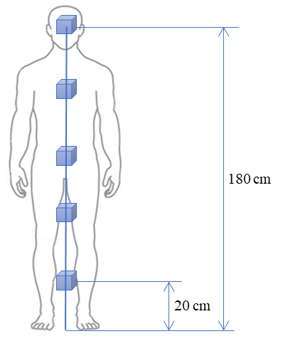
For assessments against the NS-based reference levels, \(ER_{NS-ERL}\) shall be evaluated at each measurement location in accordance with section 7.2. The arithmetic mean of the results shall be taken as the spatially-averaged NS-based exposure ratio contribution from the assessment. Instruments capable of performing automated E-field measurements and computing the spatially-averaged result may be used, provided the probe moves uniformly through the fields at a rate that yields reliable and conservative results given the time-varying nature of the emissions.
When performing an assessment against the SAR-based reference levels, it must first be demonstrated that the \(ER_{SAR-RL}\) values obtained at each location in accordance with section 7.2 are exclusively dictated by the E-field. If so, the arithmetic mean of the results shall be taken as the spatially-averaged SAR-based exposure ratio contribution from the assessment.
B.3. H-field
In the case of H-field spatial averaging, it is assumed that the source is a loop or coil antenna. Averaging is performed over a planar area, which is parallel to the plane of the antenna aperture and positioned such that the worst-case exposure is captured. The dimensions of the averaging area should match those of the source antenna; however, at no point shall the height and width of the area exceed 60 cm and 30 cm, respectively, as these dimensions approximate the average size of a human torso.
Measurements shall be performed on a nine-point grid as depicted in figure B2. The locations of the outer points are uniformly spaced based on the dimensions of the source antenna or human torso. The central measurement shall be taken at the location of maximum exposure within the averaging area, unless this coincides with one of the measurement locations, in which case the central measurement shall be performed at the geometric centre of the averaging area.
Figure B2: Illustration of discrete sampling requirements when performing H-field spatial averaging
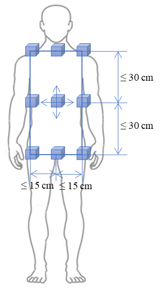
If the source antenna dimensions are less than 60 cm high and 30 cm wide, the spatial averaging area will vary. The outer points of the measurement grid shall not exceed the maximum dimensions of the source antenna. If the dimensions of the source antenna are less than three times those of the associated probe antenna(s), the number of grid points shall be reduced to five, with the middle measurement points of the outer perimeter being omitted and the central measurement being performed in the geometric centre of the grid.
For source antennas with dimensions exceeding 60 cm high and 30 cm wide, spatial averaging shall be performed over grids for which the corner measurements are maximized. This may require multiple grid locations over the area of the source antenna aperture. The maximum H-field is often near the edge of the antenna aperture, thus coinciding with the perimeter of the grid. In this case, the central measurement shall be performed at the geometric centre of the grid.
For NS-based assessments, \(ER_{NS-HRL}\) values shall be evaluated at each measurement location in accordance with section 7.2. The arithmetic mean of the results shall be taken as the spatially-averaged NS-based exposure ratio contribution from the assessment.
When performing an assessment against the SAR-based reference levels, it must first be demonstrated that the \(ER_{SAR-RL}\) values obtained at each location in accordance with section 7.2 are exclusively dictated by the H-field. If so, the arithmetic mean of the results shall be taken as the spatially-averaged SAR-based exposure ratio contribution from the assessment.
Annex C. Additional requirements for measurement-based, time-domain assessments against the SAR-based reference levels
This annex provides additional requirements for measurement-based, time-domain assessments against the SAR-based reference levels.
C.1. Assessment overview
The proposed procedure for evaluating the SAR-based exposure ratio can be summarized as follows:
- Apply a sliding fast Fourier transform (FFT) to H(t) and E(t), the measured H- and E-field vector magnitudes. Provided that considerations such as aliasing, truncation/spectral leakage and scaling are properly addressed, the RMS amplitude spectra associated with H(t) and E(t) can be obtained for the time interval over which the FFT was applied.
- For each set of spectra, isolate the frequency range associated with the assessment, and evaluate the exposure ratio corresponding to that time interval.
- Apply a rolling six-minute average to these exposure ratios, to yield the SAR-based exposure ratio for the emission(s) under consideration.
C.2. FFT requirements
The following shall be considered when applying a sliding K-point FFT to H(t) and E(t):
- The time interval over which each FFT is performed, denoted by Tw, shall be large enough to ensure sufficient frequency resolution for the assessment. A condition similar to \(T_{w}\geq 100/ \sqrt{f_{low}f_{high}} \) is recommended, where flow and fhigh are the lowest and highest frequencies associated with the assessment, respectively.
- The sampling frequency, denoted by fs, shall be high enough to prevent aliasing and foldover effects, i.e. more than twice the highest frequency associated with the assessment. A condition similar to \( f_{s}\geq 2(f_{high}+f_{low}) \) is recommended.
- The number of time samples associated with the FFT is given by \( N=\left \lfloor f_{s}T_{w} \right \rfloor \), where \( \left \lfloor * \right \rfloor \) denotes the “floor” or “round down” operation. The condition K≥N shall be met. It is recommended that K be the next power of 2 relative to N.
- The effects of truncation and spectral leakage shall be prevented. Scaling the time samples by the Hann window is recommended for this purpose.
- The time interval between successive FFT evaluations, denoted by Tslide, shall be small enough to ensure the dynamics of the measured fields are fully and continuously captured. It is recommend to have \(T_{slide}\leq 0.1T_{w} \) if the Hann window is being applied.
C.3. Isolating the assessment frequency range and FFT scaling
Let \(H_{w}[k] \) and \(E_{w}[k] \) denote the discrete spectra obtained via K-point FFT of H(t) and E(t) over the most recent time interval Tw, where k is the frequency index. The frequency range associated with the \(H_{w}[k] \) and \(E_{w}[k] \) extends from 0 Hz to fs, with fs/2 to fs representing negative frequency content. As the assessment is performed over a limited frequency range (i.e. 100 kHz to 10 MHz), the corresponding values of k need to be identified. The frequency corresponding to the k-th sample, denoted by fk, can be expressed as:
(18)
allowing k to be mapped to frequency. Let \(k_{min,H} \) and \(k_{min,E} \) denote minimum values of k for which fk is within the H- and E-field assessment frequency ranges, respectively. Similarly, let kmax denote the maximum value of k for which \(f_{k} ≤ f_{high} \).
For the assessment frequency ranges, the RMS magnitude spectra associated with Hw [k] and Ew [k], denoted by \(H_{w,rms} [k] \) and \(E_{w,rms} [k] \) , can be expressed as:
(19)
and
(20)
where \(a \) is the window scaling factor, e.g. \(a=0.5 \) for the Hann window.
C.4. Evaluating the SAR-based exposure ratio
The SAR-based exposure ratio associated with the time interval (Tw) over which the most recent FFT was performed, denoted by \(ER_{SAR-RL,w} \), can be expressed as:
(21)
where \(H_{SAR-RL} [f_{k}] \) and \(E_{SAR-RL} [f_{k}] \) are the values of the SAR-based H-field and E-field reference levels at fk, respectively.
The SAR-based exposure ratio associated with the assessment, \(ER_{SAR-RL} \), is given by applying a rolling six-minute time-average to \(ER_{SAR-RL,w} \), and identifying the maximum value over any six-minute period.
Annex D. Additional requirements for WPT implementations
This annex provides additional requirements specific to WPT implementations.
D.1. General
The EUT associated with a WPT implementation is assumed to consist of one or more WPT sources and one or more WPT clients. If a WPT source is designed to work with a variety of WPT clients (e.g. a table-top charger) and does not qualify for the reduced computational assessment procedure defined in section D.3, the EUT shall include one or more representative WPT clients, such that the worst-case RF exposure is captured. In this case, rationale for the chosen WPT client(s) shall be provided in the RF exposure technical brief.
In addition to the information requested in section 5.4, the operational description of a WPT implementation shall include the following:
- The mechanism of wireless coupling for the purpose of power transfer. Common examples include, but are not limited to: inductive, capacitive, magnetic field resonance and electric field resonance.
- The power profile during operation. For each combination of WPT source and WPT client, this includes:
- the nominal and maximum transmit power of the WPT source
- the relationship between transmit power and displacement of the WPT client, in any direction, from the position and orientation yielding optimal performance
- the maximum displacement that can be tolerated in each direction before power transfer is interrupted
- the relationship between the transmitted power and the loading condition of the WPT client (e.g. battery charge level)
- If applicable, the communication protocol between the WPT source(s) and WPT client(s) for the purpose of power transfer management shall be described.
- For each relevant use-case in the context of RF exposure, the number of WPT sources and WPT clients involved shall be identified, along with the nature of user and/or bystander interaction with the system.
Note: Some devices can act as either a WPT source or a WPT client, depending on the use-case. For these devices, details for each mode of operation shall be provided.
D.2. Exposure conditions
This section provides requirements relating to exposure conditions from WPT implementations.
D.2.1. Overview
In accordance with sections 5.1 and 5.2, the key RF exposure conditions, along with the corresponding separation distances, shall be identified. For WPT implementations incorporating a single WPT source and WPT client, the exposure conditions can be broadly divided into two categories:
- exposure from the WPT system during power transfer
- direct exposure from the WPT source
Further requirements regarding these categories are provided in the following sections.
For systems incorporating multiple WPT clients and/or WPT sources, exposure conditions for all possible combinations of WPT sources and WPT clients shall be identified.
D.2.2. Exposure from the WPT system during power transfer
This exposure category can be described as follows: a WPT source is transferring power to a sufficiently aligned WPT client, while a user is nearby. Compliance shall be demonstrated for the worst-case combination of:
- transmit power, assuming 100% duty cycle
- displacement of the WPT client, in any direction where WPT is still activated, from the position and orientation yielding optimal WPT performance
- user and/or bystander position at the corresponding separation distance
Compliance shall also be demonstrated when the WPT client is optimally positioned.
The separation distance(s) for assessments against the SAR and NS-based limits shall be determined in accordance with 5.2. For consumer products such as table-top charging pads, WPT-enabled portable devices, etc., assessments against the NS-based limits shall be performed at touch position (0 cm), because the user will interact directly with one or more of the WPT devices involved. For the example of a charging pad, a user would deposit their device directly upon the pad, and may retrieve it at any point during the charging cycle.
D.2.3. Direct exposure from the WPT source
Depending on the implementation, it may be possible for a user to be directly exposed to RF energy produced by a WPT source. This may occur as one or more WPT clients move in and out of the coupling region of the WPT source over time. In the absence of a sufficiently coupled WPT client, the antenna(s) or coupling element(s) of a WPT source may continue to be energized in an effort to “search” for a viable WPT client. This may be done at a reduced duty cycle, reduced power level, or both. Compliance shall be assessed when a user is in the worst-case position, e.g. at the minimum separation distance in front of the coupling element(s) of the WPT source.
Direct exposure from a WPT source may be significant immediately following the sudden removal of a WPT client during power transfer. Depending on the time required for the WPT source to recognize the removal of the WPT client and power down, it is possible for the user to be exposed to the fields from the fully energized WPT source, representing a worst-case exposure scenario for NS (instantaneous exposure). This timing shall be provided in the RF exposure technical brief, in accordance with section 5.4.4. Compliance shall be assessed when the user is in the worst-case position e.g. at the minimum separation distance in front of the coupling element(s) of the WPT source, unless the WPT source is able to power down in less than 1 second, or it can be demonstrated that alternative measures have been taken to prevent this exposure scenario. Time-domain test plots demonstrating that the WPT source shuts down within 1 second of the test load being removed shall be included in the RF exposure technical brief.
For WPT implementations in which the user directly interacts with the devices involved, direct exposure from the WPT source shall be assessed at touch position (0 cm).
D.3. Computational assessments for small WPT implementations
A simplified and conservative computational assessment method may be applied for devices with WPT source capabilities that meet the following conditions:
- \(D_{s} ≤ 20 cm \), where Ds is the maximum linear dimension of the WPT source antenna. If the antenna consists of an array of elements (coils, electrodes, etc.), the entire array needs to meet this condition.
- The device enclosure on the side associated with WPT (e.g. the charging surface) is flat, thus accommodating a flat phantom.
If this is the case, the following procedure may be applied when performing a computational assessment:
- The EUT may be limited to the WPT source device, i.e. a representative WPT client would not be considered part of the EUT.
- The WPT source antenna shall be continuously driven by the maximum current level that the transmitter is capable of supplying.
- A flat homogeneous phantom shall be employed at touch position (0 cm), i.e. the outer surface of the phantom is in contact with the enclosure of the WPT source, with the WPT source’s charging surface facing the phantom. In addition:
- The material properties of table 3 in section 8 of this document should be used.
- The dimensions of the phantom shall be large enough that increasing them in any direction has no measurable impact of the assessment results. They should be more than twice the value of Ds in each direction; however, the depth of the phantom may be smaller if this is demonstrated not to have a measurable impact on the results.
- The phantom shall be positioned to ensure maximum exposure, e.g. centred on the WPT source antenna.
- Uncertainty analysis and model validation shall be performed as per section 8.3.5.
- The values of \(ER_{SAR-BR} \) and \(ER_{NS-BR} \) shall be evaluated in accordance with section 8.4.2, and the corresponding TERs shall be calculated.
Compliance may be demonstrated in this way, provided the following conditions are met:
- \(ER_{SAR-BR} < 0.75 \) (nominal)
- \(ER_{NS-BR} < 0.75 \) (nominal)
- \( TER_{therm} \leq 1 \)
- \(TER_{NS} \leq 1 \)
Rationale for the use of this method shall be documented in the RF exposure technical brief, along with the assessment results. When the conditions above cannot be met, a full computational analysis as per section 8 shall be provided.
D.4. Assessments against the reference levels for electric vehicle WPT implementations
This section provides requirements for assessing electric vehicle (EV) WPT implementations.
D.4.1. Applicable implementations
The requirements provided in the following sections applies to EV WPT implementations meeting the following criteria:
- the WPT source subassembly is designed to be mounted in or on the ground, forming part of a ground assembly (GA)
- the WPT client subassembly is mounted on the bottom surface of the EV, forming part of a vehicle assembly (VA)
For all other EV WPT implementations, an inquiry shall be submitted to ISED.
D.4.2. General requirements
For EV WPT implementations meeting the criteria of section D.4.1, compliance may be demonstrated by performing an assessment against the reference levels. These assessments shall be performed via measurements in accordance with section 7, or simulations using a validated computational model in accordance with section 8. If the reference levels are exceeded, an assessment against the basic restrictions is required, and an inquiry shall be submitted to ISED.
A complete assessment shall capture the NS- and SAR-based exposure ratios under the worst-case combination of:
- system configuration (e.g. single or multiple GAs and VAs)
- wireless gap and horizontal misalignment between the GA(s) and VA(s)
- charging state of the EV
- exposure condition:
- direct exposure from the GA(s), i.e. no vehicle present, if applicable
- exposure from the EV WPT system during charging, e.g. inside the vehicle, outside the vehicle, or reaching underneath the vehicle
If the GA(s) produce emissions in the range of 3 kHz to 10 MHz when the vehicle is absent (e.g. in searching for a viable WPT client), direct exposure from the GA(s) shall be assessed. In this case, the GA(s) may be treated as floor-mounted and walked-over devices, and assessed in accordance with the relevant procedure in section E.2 of annex E.
While the EV is being charged, consideration must be given to the fields surrounding the vehicle. These can be broadly divided into three distinct regions as illustrated in figure D1:
- Region 1: Under the vehicle. The highest field levels are usually observed in this region, as this is where the GA(s) and VA(s) are mounted. This is also the least accessible region during charging, and it is assumed that the most likely exposure scenario is a user or bystander reaching underneath the vehicle to retrieve or search for an object during the charging cycle.
- Region 2: Outside the vehicle. Users or bystanders can stand beside or lean against the vehicle at any point during the charging cycle. Due to the blocking provided by the chassis of the vehicle, in most cases it is expected that the highest fields would be observed near the gap between the ground and the bottom of the chassis.
- Region 3: Inside the vehicle. Users or bystanders can occupy any of the seats within the vehicle at any point during the charging cycle.
Figure D1: Illustration of an EV WPT implementation (front view)
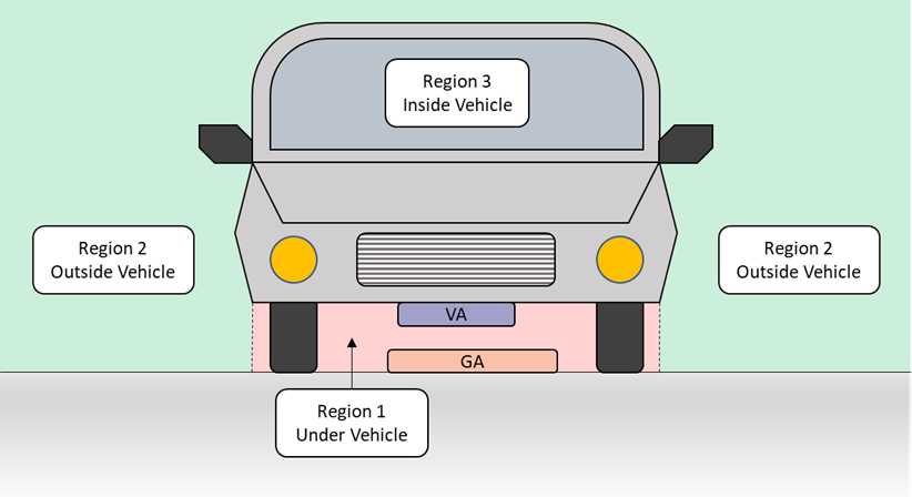
D.4.3. Region 1: Under the vehicle
The NS-based reference levels should not be exceeded when an adult or child reaches underneath the vehicle at any point during the charging cycle. Otherwise, an assessment against the basic restriction shall be performed. The H-field relaxation factor for arm exposure may be used, provided the ground clearance of the EV is such that it is not realistic or practical for an adult or child to have their head underneath the vehicle.
If sensors are used to detect the presence of living tissue or other foreign objects and reduce power accordingly, this function shall be described in the RF exposure technical brief. The coverage area of the sensor implementation shall be defined as the region within which the hand of a small child is consistently and reliably detected, and the appropriate safety measures are triggered. This shall be validated experimentally, taking into account any hysteresis effects associated with the triggering, as well as the operating conditions of the EV WPT system (e.g. system configuration, wireless gap, misalignment, loading conditions). The validation results shall be used to determine the worst-case exposure condition(s) associated with Region 1. These conditions shall be noted in the RF exposure technical brief, along with the corresponding assessment results.
D.4.4. Region 2: Outside the vehicle
This region extends from the outer surface of the vehicle chassis, neglecting protrusions such as side mirrors, as illustrated in figure D1, above, and in figure D2, below. The NS-based reference levels should not be exceeded anywhere in Region 2. Otherwise, an assessment against the basic restriction shall be performed. Relaxation factors shall not be applied for NS-based assessments in this region.
If the EV WPT system produces emissions above 100 kHz, an assessment against the SAR-based reference levels shall be performed in Region 2. As for NS, the SAR-based reference levels should not be exceeded anywhere in Region 2; however, the relaxed SAR-based H-field reference level for leg exposure, shown in table 2 (in section 5 of this document), may be applied below 85 cm from the ground. If the reference levels are exceeded, an assessment against the basic restrictions shall be performed.
Figure D2: Illustration of an EV WPT implementation (top view)
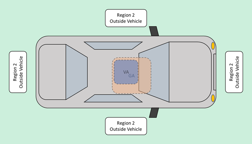
D.4.5. Region 3: Inside the vehicle
Inside the vehicle cabin, assessments shall be made against the NS- and, if applicable, the SAR-based reference levels. These levels should not be exceeded anywhere within the cabin. Otherwise, an assessment against the basic restrictions shall be performed. The SAR-based assessment may focus on the driver and passenger seating areas. The following shall be considered in the application of H-field relaxation factors:
- Exposure of the feet resting on the floor of the cabin: The H-field relaxation factors for hand/foot exposure may be applied up to a height of 10 cm from the floor of the cabin.
- Exposure of the legs while seated: The H-field relaxation factors for leg exposure may be applied up to a height of 50 cm from the floor of the cabin.
- Head and torso exposure while seated: This covers heights above 50 cm from the floor of the cabin, and H-field relaxation factors are not applicable.
Annex E. Additional requirements for various device types
This annex provides additional requirements for a number of common device types, with the exception of WPT implementations (which are covered in annex D).
E.1. Floor-standing devices
This section provides additional requirements for floor-standing devices, examples of which include:
- electronic article surveillance (EAS) systems, which typically consist of antennas set on each side of an opening at the entrance or exit of a store that are used to detect tags that pass through the area
- radiofrequency identification (RFID) turnstiles, which typically require that the user pass an RFID card over the turnstile to gain access to the entrance way
- walk-through devices, which are typically metal detectors that the human body would pass through
E.1.1. Torso grid positioning for H-field spatial averaging in assessments against the reference levels
For floor-standing devices with antennas that are taller than 145 cm and wider than 30 cm, the torso grid shall be 85 cm above the floor and positioned such that the right or left edge of the grid is at the location of highest exposure. An example illustration of torso grid positioning is shown in figure E1.
Figure E1: Example illustration of the torso grid positioning for H-field spatial averaging when the antenna(s) of a floor-standing EUT are taller than 145 cm and wider than 30 cm
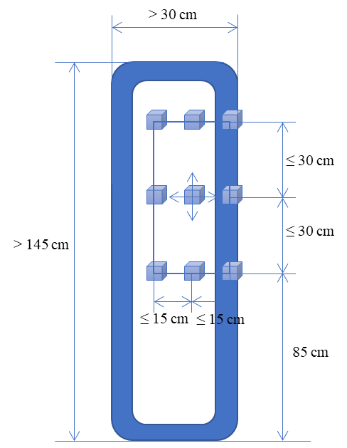
For floor-standing devices with antennas that are smaller than the torso grid, or that are positioned such that they are lower than 85 cm and only cover a portion of the torso grid, the spatial averaging area shall remain above 85 cm, and averaging shall not be performed beyond the dimensions of the antenna(s).
E.2. Floor-mounted devices
This section provides additional requirements for floor-mounted devices, examples of which include:
- floor-mounted and walked-over devices, such as timing devices used during races, where the runner moves over an antenna on the ground that reads an RFID device worn by the runner
- floor-mounted devices that are obstructed by an object (i.e. devices that are placed on the floor and are active while an object is over its surface); the exposure condition is to a human in the area beside the object
Note: Small floor-operated devices, i.e. any of the above devices, or simply a device that is placed on the floor and uses RFID to perform some action, may be treated as table-top devices and assessed in accordance with section E.5.
E.2.1. Assessment locations
Exposure from any floor-mounted device that can be walked over by the general public shall be assessed from 0 cm to 180 cm, along the axis yielding the worst-case results.
For floor-mounted devices that are obstructed by an object (i.e. members of the general public cannot walk over the device during operation), the assessment shall be performed without the obstructing object in place. This may require the use of test-mode software. Exposure shall be evaluated at a sufficient number of radials around the perimeter of the typical obstructing object to provide a minimum separation of 22.5° between each radial. At each radial, exposure shall be evaluated from 0 cm to 180 cm above the floor for non-metallic obstructions, and from 0 cm to the average exposure height for metallic obstructions. In the latter case, the average exposure height and corresponding rationale shall be provided in the RF exposure technical brief.
E.2.2. Spatial averaging
Spatial averaging shall not be applied when performing an assessment of a floor-mounted device.
E.2.3. Limb relaxation factors
In the case of floor-mounted and walked-over devices, the foot relaxation factors may be applied from 0 cm to 10 cm. The leg relaxation factors may be applied from 10 cm to 85 cm. Above 85 cm, relaxation factors shall not be applied.
For floor-mounted devices that are obstructed by an object (i.e. members of the general public cannot walk over the device during operation), the leg relaxation factors may be applied at heights up to 85 cm. Above 85 cm, relaxation factors shall not be applied.
E3. Hand-held devices
This section provides additional requirements for hand-held devices, examples of which include:
- hand-held devices used to scan a human body, such as metal detector wands (these devices are used in close contact with the human body and the exposure condition is focused on the body being scanned and not as focused on the user of the equipment)
- hand-held devices used to scan an object, such as hand-held RFID readers (these devices are typically used to scan objects instead of a human body, and so the main goal is to assess RF exposure in the extremities of the user, i.e. their hand(s))
E.3.1. Assessment locations
For hand-held devices used to scan the human body, the assessment shall be performed at a height of 130 cm. The assessment should be performed in all orientations surrounding the hand-held device. Alternatively, the hand-held device may be tested as a table-top device on three orthogonal axes, following the procedure in section E.5.
For hand-held devices used to scan an object, the assessment shall be performed at a height of 100 cm. The assessment shall focus on the area where the hand of the user would be placed and at the corresponding separation distance. If the regions of maximum exposure are not accessible due to the construction of the device, a computational assessment may be performed. Alternatively, a measurement-based assessment may performed on a disassembled device, provided the behaviour of the transmitters is not significantly impacted by the disassembly. This shall be demonstrated in the RF exposure technical brief.
E.4. Wall-mounted devices
This section provides additional requirements for wall-mounted devices. In this frequency range, these are typically devices used for RFID purposes (e.g. they are mounted on the wall close to a door and used to read an RFID card).
Wall-mounted devices may be assessed in accordance with the procedure provided for table-top devices in section E.5, but at the separation distances associated with the device. RF exposure evaluations should only be necessary in the directions away from the wall, provided the construction of the wall ensures a much larger separation distance than those identified for the device as per section 5.2.
E.5. Table-top devices
This section provides additional requirements for table-top devices.
E.5.1. Test set-up
If the device is permanently installed within a table-top, the assessment shall be performed assuming the user is positioned for worst-case exposure, e.g. at the closest edge of the table relative to the device. Otherwise, the device shall be placed at the edge of a non-metallic table that is 80 cm high. Support equipment used to operate the device shall also be placed along the edge, with a minimum of 10 cm between each component.
The following shall be demonstrated:
- The hands of the user are not over-exposed when interacting with the device during operation. The NS-based assessment shall be performed at touch position (0 cm), while the SAR-based assessment shall be performed at a conservative separation distance based on six-minute exposure in accordance with section 5.2. For assessments against the H-field reference levels, the hand/foot relaxation factors may be applied.
- The legs of the user are not over-exposed when positioned beneath the table-top, if applicable. The minimum expected distance between the bottom surface of the table-top and the legs may be applied during the assessment, provided the value and rationale for this distance is documented in the RF exposure technical brief. For assessments against the H-field reference levels, the leg relaxation factors may be applied.
- The core or torso of the user is not over-exposed. The distance between the torso and the edge of the table shall be 0 cm for the NS-based assessment. For the SAR-based assessment, a conservative distance shall be considered based on six-minute exposure in accordance with section 5.2. Relaxation factors shall not be applied.
Note: All three conditions may be satisfied by demonstrating compliance with the un-relaxed reference levels at touch position (0 cm) on all sides of the EUT.
Annex F. Bibliography
Institute of electrical and electronics engineers (IEEE) C95.3.1-2010, IEEE Recommended Practice for Measurements and Computations of Electric, Magnetic, and Electromagnetic Fields with Respect to Human Exposure to Such Fields, 0 Hz to 100 kHz, May 2010.
Institute of electrical and electronics engineers (IEEE) C95.3-2002, IEEE Recommended Practice for Measurements and Computations of Radio Frequency Electromagnetic Fields With Respect to Human Exposure to Such Fields, 100 kHz-300 GHz, January 2003.
International Electrotechnical Commission (IEC) PAS 63184, Assessment methods of the human exposure to electric and magnetic fields from wireless power transfer systems - Models, instrumentation, measurement and numerical methods and procedures (frequency range of 1 kHz to 30 MHz).
International Electrotechnical Commission (IEC) TS 62764-1, Measurement procedures of magnetic field levels generated by electronic and electrical equipment in the automotive environment with respect to human exposure - Part 1: Low frequency magnetic fields.