
Issue 6
December 15, 2023
Contents
1. Scope
2. References
3. Definitions, abbreviations/acronyms and quantities
4. Certification requirements
5. Exposure limits
6. Exemption limits for routine evaluations
7. Evaluation methods
8. Total exposure
Annex A: RF exposure technical brief cover sheet
Annex B: Declaration of RF exposure compliance for exemption from routine evaluation limits
Annex C: Sensor validation
Annex D: Nerve stimulation (NS) exemption limits examples (informative)
Preface
Radio Standards Specification 102, issue 6, Radio Frequency (RF) Exposure Compliance of Radiocommunication Apparatus (All Frequency Bands), sets out the requirements and measurement techniques for evaluating radio frequency exposure compliance of radiocommunication apparatus designed to be used within the vicinity of the human body. RSS-102, issue 6, replaces RSS-102, issue 5, dated March 19, 2015.
The main changes are listed below:
- New architecture that reformats RSS-102 as a series of standards:
- RSS-102 remains the main standard to which RF exposure compliance is evaluated and to which certification is granted
- Existing Supplementary Procedures (SPR) documents will be rescinded, and their contents incorporated into specific parts of RSS-102 measurements or simulations companion standards
- A series of new companion standards that need to be used in conjunction with RSS-102 to assess compliance either via measurements or simulations:
- RSS-102.NS.MEAS, Measurement Procedure for Assessing Nerve Stimulation (NS) Compliance in Accordance with RSS-102
- RSS-102.SAR.MEAS, Measurement Procedure for Assessing Specific Absorption Rate (SAR) Compliance in Accordance with RSS-102
- RSS-102.APD.MEAS, Measurement Procedure for Assessing Absorbed Power Density (APD) Compliance in Accordance with RSS-102 (currently in development)
- RSS-102.IPD.MEAS, Measurement Procedure for Assessing Incident Power Density (IPD) Compliance in Accordance with RSS-102
- RSS-102.FRL, Procedure for Assessing Field Reference Level (FRL) Compliance in Accordance with RSS-102 (currently in development)
- RSS-102.NS.SIM, Simulation Procedure for Assessing Nerve Stimulation (NS) Compliance in Accordance with RSS-102
- RSS-102.SAR.SIM, Simulation Procedure for Assessing Specific Absorption Rate (SAR) Compliance in Accordance with RSS-102 (currently in development)
- RSS-102.APD.SIM, Simulation Procedure for Assessing Absorbed Power Density (APD) Compliance in Accordance with RSS-102 (currently in development)
- RSS-102.IPD.SIM, Simulation procedure for assessing incident power density (IPD) compliance in accordance with RSS-102
- New exemption limits for nerve stimulation (NS)
- New exemption limits for absorbed power density (APD)
- Revised exemption limits for specific absorption rate (SAR)
- New requirements to assess compliance of hand SAR and APD during voice calls
- Revised maximum separation distance for SAR
- New requirements for sensor validation
- Integration of the RSS-216 RF exposure requirements to assess WPT devices
Inquiries may be submitted by one of the following methods:
- Online using the General Inquiry form (in the form select the Directorate of Regulatory Standards radio button and specify “RSS-102” in the General Inquiry field).
- By mail to the following address:
Innovation, Science and Economic Development Canada
Engineering, Planning and Standards Branch
Attention: Regulatory Standards Directorate
235 Queen St
Ottawa ON K1A 0H5
Canada - By email to consultationradiostandards-consultationnormesradio@ised-isde.gc.ca
Comments and suggestions for improving this standard may be submitted online using the Standard Change Request form, or by mail or email to the above addresses.
All Innovation, Science and Economic Development Canada publications related to spectrum and telecommunications are available on the Spectrum management and telecommunications website.
Issued under the authority of
the Minister of Innovation, Science and Industry
____________________________________
Martin Proulx
Director General
Engineering, Planning and Standards Branch
1. Scope
This Radio Standards Specification (RSS) sets out the requirements, measurement and simulation techniques to be employed for evaluating radio frequency (RF) exposure compliance of radiocommunication apparatus (Category I and Category II equipment), which are designed to be used within the vicinity of the human body. This standard applies to either:
- radiocommunication apparatus having an integral antenna
- systems requiring licensing with detachable antennas offered with the transmitters
- licence-exempt transmitters with detachable antennas, as defined in RSS-Gen, General Requirements for Compliance of Radio Apparatus
The requirements within this document also apply to wireless power transfer (WPT) source subassemblies, including Type 1, which are classified as interference-causing equipment.
This standard shall be used in conjunction with other applicable RSSs. Before the equipment certificate is granted by Innovation, Science and Economic Development Canada (ISED) or by a recognized certification body (CB), the applicant shall demonstrate compliance with all applicable standards, including this one.
1.1 Regulatory requirements
Manufacturers, importers, distributors and vendors have a legal obligation to ensure that Category I radio apparatus introduced in the Canadian marketplace have been certified and comply with applicable technical standards. As per the requirements set forth in section 4(3) of the Radiocommunication Act, “No person shall manufacture, import, distribute, lease, offer for sale or sell any radio apparatus, interference-causing equipment or radio-sensitive equipment for which technical standards have been established under paragraph 6(1)(a), unless the apparatus or equipment complies with those standards.” As per the requirements set forth in RSS-Gen, “No person shall import, distribute, lease, offer for sale, or sell Category I radio apparatus in Canada unless they are listed on ISED's radio equipment list (REL).”
It is the responsibility of proponents and operators of antenna system installations to ensure that all radiocommunication and broadcasting installations comply with Health Canada’s Safety Code 6 at all times. This includes the consideration of combined effects of nearby installations within the local radio environment. These requirements are specified in Client Procedures Circular CPC-2-0-03, Radiocommunication and Broadcasting Antenna Systems.
1.2 Transition period
RSS-102, issue 6, will be in force as of its publication on ISED’s website. However, a transition period of 12 months following its publication is provided, within which compliance with issue 5 or issue 6 of RSS-102 is accepted. After this period, only applications for the certification of equipment under RSS-102, issue 6, will be accepted. Furthermore, after this transition period, equipment that is manufactured, imported, distributed, leased, offered for sale or sold in Canada shall comply with RSS-102, issue 6.
A copy of RSS-102, issue 5, my be requested by emailing consultationradiostandards-consultationnormesradio@ised-isde.gc.ca.
2. References
This section lists the normative references and other external documents referred to in this standard.
2.1 Normative publications
The documents that are listed on the Radio Frequency (RF) Exposure Normative References and Acceptable Knowledge Database web page shall be consulted as applicable and available, in conjunction with this RSS.
2.2 Priority of normative references
The applicant shall follow the applicable test methods based on the priority list of documents outlined below:
- this RSS-102
- International Electrotechnical Commission (IEC) and Institute of Electrical and Electronics Engineers (IEEE) standards referenced in this document
- other recognized procedures, such as Federal Communications Commission (FCC) RF exposure knowledge database (KDB) procedures, referenced on the Acceptable knowledge database, other supplementary procedures and notices on ISED’s website
The applicant can consult with ISED if guidance on the priority list of documents is required for the type of radiocommunication apparatus for which regulatory compliance is sought. Requests may be submitted online through the submission of a General Inquiry or through any other method as outlined in the preface.
3. Definitions, abbreviations/acronyms and quantities
This section provides definitions and abbreviations/acronyms for terms used in this document, as well as the symbols/units used for quantities.
3.1 Definitions
The following definitions apply to RSS-102 and its related documents.
Basic restrictions: The electric field, magnetic field, or power density limits that are assessed inside the body, which should not be exceeded. The basic restrictions are primarily specified in terms of internal electric field strength, the specific absorption rate and absorbed power density.
Body-worn (or body-mounted) device: A wireless transceiver that is designed to be worn or carried on the body of a person. This includes wireless communication devices that are attached to or integrated in clothing or accessories such as lanyards, clothing-integrated devices, or belts.
Controlled use (controlled environment): This is the type of approval given to a device that is intended to be used by persons who are fully aware of, and can exercise control over, their exposure. Controlled use devices are not typically available via sales channels/platforms offered to the general public, nor intended for use by the general public. In addition, they are not installed in public areas.
Computational electromagnetic modelling: A method consisting of using computer simulations to determine compliance against the RSS-102 limits. In the RSS-102 family of standards, the terms computational modelling and simulation are interchangeable.
Device: A sample unit that is representative of the equipment for which certification is sought. The actual product may be employed if it is available.
Field reference level (FRL) exposure evaluation: A method employed to evaluate the RF field strength or power density generated by a device. Field reference level exposure evaluation is required if the separation distance between the device and the user or bystander is greater than 20 cm. This was referred to as ‘RF exposure evaluation’ in previous versions of RSS-102.
General public use (uncontrolled environment): The type of approval given to a device that can be used by the general public.
Mobile device: A transmitting device designed to be used in non-fixed locations such that a separation distance greater than 20 centimetres is normally maintained between the RF source's radiating structure(s) and the body of the user and/or bystander.
In the context of the RSS-102 family of standards, a portable device is not the same as a mobile device (see definition of a portable device below).
Output power: The larger of the maximum conducted power or equivalent isotropic radiated power (EIRP), source-based and time-averaged.
Operating state: The discrete set of configurations and modes of operation for a specific exposure condition. The operating state contains the following parameters:
- modes of operation (e.g. voice mode, hotspot)
- exposure condition
- SAR averaging volume (1 g or 10 g)
- applicable testing distance
The operating state is also known as a device state index in some implementations.
Portable device: A transmitting device designed to be used in non-fixed locations such that the RF source's radiating structure(s) is (are) at 20 centimetres or less from the body of the user and/or bystander.
In the context of this RSS, a mobile device is not the same as a portable device (see definition of a mobile device above).
Radio frequency (RF) exposure: The human exposure from any and all combinations of nerve stimulation (NS), specific absorption rate (SAR), absorbed power density (APD), incident power density (IPD) and field reference level (FRL).
Reference level: The electric field, magnetic field, or power density limits that are assessed external to the body.
Separation distance: The minimum test separation distance is based on the smallest distance between any part of the body or limb of a user or bystander and the antenna, radiating structures, or the outer surface of the device, according to the most conservative exposure condition for the applicable module or host platform test procedure requirements.
Specific absorption rate (SAR) evaluation: The method used to evaluate the SAR levels from a device by physical measurement or simulation by applying computational electromagnetics modelling techniques. SAR evaluation is required if the separation distance between the user or bystanders and the device is less than or equal to 20 cm.
Specific absorption rate (SAR): The rate of RF energy absorbed in tissue, per unit mass.
Table top device: An apparatus that is placed on a table that is powered through the AC mains power. The user may or may not interact with the apparatus while seated at the table. Note: A table top device is sometimes referred to as a desktop device.
Tune-up tolerance: The range of expected maximum output power variations from the rated nominal maximum output power specified for the product or wireless mode.
Wireless power transfer (WPT): The transfer of energy from one or more source devices to one or more client devices through electromagnetic waves or fields using magnetic fields (inductive or resonant), electric field (capacitive or resonant), or radiative means, with no electrical contact between the source and client device(s), for the purpose of powering and/or charging the client device(s) wirelessly.
WPT client: A device capable of receiving power wirelessly from a WPT source.
WPT source: A device directly connected (i.e. through a wired connection) to a power source (e.g. AC mains, a battery or some other source of internal or external electrical power), which is capable of wireless power transfer to one or more WPT clients.
3.2 Abbreviations/acronyms
This document uses the following abbreviations and acronyms:
- APD
- Absorbed power density
- CB
- Certification body
- CAB
- Conformity assessment bodies
- CEM
- Computational electromagnetics
- EIRP
- Effective isotropic radiated power
- ER
- Exposure ratio
- EUT
- Equipment under test
- FRL
- Field reference level
- IEC
- International Electrotechnical Commission
- IEEE
- Institute of Electrical and Electronics Engineers
- IPD
- Incident power density
- ISED
- Innovation, Science and Economic Development Canada
- Hz
- Hertz
- LPD
- Localized power density
- N/A
- Not applicable
- NS
- Nerve stimulation
- PD
- Power density
- pIPD
- Spatial peak power density
- psPD
- Peak spatial-averaged power density
- RF
- Radio frequency
- RL
- Reference level
- RMS
- Root mean square
- SAR
- Specific absorption rate
- SI
- International system of units
- SPLSR
- SAR to peak location separation ratio
- TPD
- Time-averaged PD
- TAS
- Time averaged SAR
- TER
- Total exposure ratio
- WPT
- Wireless power transfer
3.3 Quantities
Table 1 lists the quantities employed throughout this document along with their internationally accepted SI units (where applicable).
Table 1: Quantities
| Quantity | Symbol | Unit |
|---|---|---|
| Magnetic flux density | B | tesla (T) |
| Base unit of length | m | metre (m) |
| Effective isotropic radiated power | EIRP | watts (W) |
| Electric field strength | E | volts per metre (V/m) |
| Exposure ratio | ER | unitless |
| Frequency | f | hertz (Hz) |
| Mass | g | grams (g) |
| Magnetic field strength | H | amperes per metre (A/m) |
| Current | I | amperes (A) |
| Total exposure ratio | TER | unitless |
| Turns | n | unitless |
| Permeability of free space | μ0 | 1.25663706212×10⁻⁶ (N/A2) newton per ampere squared |
| Power | W | watts (W) |
| Specific absorption rate | SAR | watts per kilogram (W/kg) |
| Voltage | V | volts (V) |
| Wavelength | λ | metre (m) |
Note that common SI prefixes are permitted to be employed with the quantities outlined in table 1, where appropriate.
4. Certification requirements
This section specifies the certification requirements.
4.1 General
Compliance assessments in accordance with the guidance provided herein shall be conducted by a wireless device testing laboratory, which is recognized by ISED. A list of these laboratories is available on ISED’s Wireless Device Testing Laboratories website.
4.2 Application for certification
Compliance with this RSS shall be evaluated in conjunction with the RSS(s) applicable to the frequency band and/or technology that pertains to the equipment for which certification is sought. Devices with a variety of operating characteristics (i.e. subject to NS, SAR, APD, IPD, and/or FRL) shall require certification through the appropriate combination of these per the associated documents outlined in section 2.
4.3 RF exposure technical brief
This section specifies the requirements for the RF exposure technical brief.
4.3.1 General
The applicant shall prepare an RF exposure technical brief that contains information related to the completed evaluations required for the device. Detailed requirements are provided in each applicable document as outlined in sections 2 and 7.
The RF exposure technical brief shall demonstrate that the requirements of this standard have been met and that the appropriate measurement/simulation methods or calculations have been used.
For devices intended for controlled use, the RF exposure technical brief shall also include device operational guidelines that meet the requirements of section 4.5 for user exposure awareness and control.
4.3.2 RF exposure technical brief cover sheet
The information found in the RF exposure technical brief cover sheet (refer to annex A) shall be taken from the RF exposure technical brief and associated documents as outlined in section 2. The information provided therein shall clearly support the compliance claim.
4.4 Certification process
To obtain certification under this standard, the certification application shall be accompanied by the duly completed and signed RF exposure technical brief cover sheet (refer to annex A). However, if the device in question meets the limits of section 6 for exemption from routine evaluation, only a signed declaration of compliance needs to be submitted (refer to annex B).
In addition, submission of the technical brief(s) is required for certification. The submission shall include the appropriate completed technical brief cover sheet(s).
4.5 Manuals requirements
The following sections outline the requirements associated with the contents of a device’s manuals.
4.5.1 User and installation manual(s) requirements
The applicant is responsible for providing proper instructions to the user of the radio device and any usage restrictions including limits of exposure duration. The user manual shall provide installation and operating instructions, as well as any special usage conditions (e.g. proper accessory requirements, including the proper orientation of the device in the accessory and maximum antenna gain in the case of detachable antenna), in order to ensure compliance with applicable limits. For instance, the compliance separation distance shall be clearly stated in a prominent location in the user manual.
All device operating modes and installations, as specified in the user manual (and installation manual, where applicable), shall be supported by the test configurations and the test results. Applying instructions as a substitute for providing test results is unacceptable. Caution statements or warning labels are only acceptable for alerting users from certain unintended use conditions that are not required for normal operation modes.
The user manual for devices intended for controlled use shall include:
- information relating to the operating characteristics of the device
- the operating instructions to ensure compliance with applicable limits
- information on the installation and operation of accessories to ensure compliance with applicable limits and
- contact information where the user can obtain Canadian information on RF exposure and compliance
4.5.2 Module integration manual
In cases where module integration will be performed by the host manufacturer, the module manufacturer shall provide a detailed module integration manual with specific instructions. These specific instructions will detail how to configure all of the control and operating parameters that are accessible by the host product for power control to ensure host compliance with the requirements of RSS-102.
When the module is only approved for use by the module manufacturer or specific host manufacturers with whom the module manufacturer will directly engage, the module integration manual may be simplified. In the certification filing, detailed information, including all key configurable parameters, shall be included in the operational description.
4.6 Quality control and post-certification investigations/audits
ISED conducts market surveillance compliance audits and compliance investigations of radiocommunication apparatus placed on the Canadian market (manufactured, imported, distributed, leased, offered for sale, or sold) after certification. In these cases, the certificate holder may be asked to provide ISED records of the quality control process and any other relevant information that would help identify issues in the event of an investigation of non-compliance. It is expected that all certificate holders will be able to demonstrate a quality control process used for production inspection and testing in accordance with good engineering practices.
5. Exposure limits
This section outlines the exposure limits.
5.1 General
Through this standard, ISED adopts Health Canada’s RF exposure guideline entitled Limits of Human Exposure to Radiofrequency Electromagnetic Energy in the Frequency Range from 3 kHz to 300 GHz (Safety Code 6) and its Notice: Localized human exposure limits for radiofrequency fields in the range of 6 GHz to 300 GHz.
Exposure limits are separated in two categories:
- basic restrictions (section 5.2)
- reference levels (section 5.3)
Each of these two categories is further subdivided into two subcategories based on the exposure environment: controlled use and uncontrolled use. Uncontrolled use devices are defined as devices for which users have not received proper RF field awareness/safety training and have no means to assess or, if required, to mitigate their exposure to RF fields.
A device would be considered as a controlled-use device when the following criteria are met:
- the user manual requirements of section 4.5 have been met
- the installation manual has been provided and contains sufficient information to ensure normal usage will be maintained
- the device will be installed in a location or used in an environment that is either inaccessible to the general public or the proximity between the device and the general public is maintained by the user
- the device will not be made available or sold to the general public
- the user(s) of the device will undergo proper RF field awareness/safety training
For devices intended for controlled use, the RF exposure technical brief shall also include device operational guidelines that meet the controlled-use requirements of section 4.5.
5.2 Basic restrictions
The basic restrictions outlined in the following sections are based on Health Canada’s Safety Code 6 and its Notice. Any updates to Safety Code 6 and/or its Notice will supersede the values outlined herein.
5.2.1 Internal electric field
The limits for the internal electric field strength are intended to prevent the occurrence of NS. The basic restrictions for internal electric field strengths in excitable tissues, as shown in table 2, shall not be exceeded for frequencies between 3 kHz and 10 MHz, inclusive.
In situations where the determination of internal electric field strength is not possible or practical by measurement or simulation, external unperturbed field strength assessment shall be carried out and the reference levels outlined in section 5.3.1 shall be respected.
Table 2: Internal electric field strength basic restrictions (3 kHz to 10 MHz)
| Condition | Instantaneous RMS internal electric field strength (VRMS/m) (any part of the body) |
|---|---|
|
Uncontrolled environment |
1.35 x 10⁻⁴ f |
|
Controlled environment |
2.7 x 10⁻⁴ f |
Note: ƒ is frequency in Hz.
5.2.2 SAR
The SAR limits are summarized in table 3 .
Table 3 : SAR basic restrictions limits (100 kHz to 6 GHz)
| Body region | Uncontrolled environment average SAR (W/kg) | Controlled environment average SAR (W/kg) | Averaging time (minutes) | Averaging mass (g) |
|---|---|---|---|---|
|
Whole body |
0.08 |
0.4 |
6 |
whole body |
|
Localized head, neck and trunk |
1.6 |
8 |
6 |
1 |
|
Localized limbs |
4 |
20 |
6 |
10 |
5.2.3 Localized APD
The localized APD limits are summarized in table 4 .
Table 4 : Localized APD basic restrictions limits (6 GHz-300 GHz)
| Exposure scenario | Local APD (W/m2) | Exposure duration (minutes) |
|---|---|---|
|
Uncontrolled environment |
20 |
6 |
|
Controlled environment |
100 |
6 |
Local APD shall be averaged over a square 4 cm2 surface area of the body.
For localized APD above 30 GHz, an additional constraint, the spatial peak exposure, shall be imposed. The spatial peak is:
- two times the limits of the 4 cm2 restrictions
- not averaged over an area
Refer to Health Canada’s Safety Code 6 and its Notice for relevant notes and additional information.
5.3 Reference levels
The following sections summarize the reference levels associated with NS, SAR and RF field strengths from 3 kHz to 300 GHz.
5.3.1 Electric and magnetic field strength levels (3 kHz to 10 MHz)
The electric and magnetic field strength reference levels for devices employed by the general public (uncontrolled environment) and controlled-use devices (controlled environment) are summarized in table 5 and table 6.
Table 5 : Electric field strength reference levels
| Frequency range (MHz) | Reference level basis | Reference level (ERL) for uncontrolled environment (VRMS/m) | Reference level (ERL) for controlled environment (VRMS/m) | Reference period |
|---|---|---|---|---|
|
0.003 -10 |
NS |
83 |
170 |
Instantaneous |
|
1.10-10 |
SAR |
87/ f 0.5 |
N/A |
6 minutes |
|
1.29-10 |
SAR |
N/A |
193/ f 0.5 |
6 minutes |
Note: f is frequency in MHz.
Table 6 : Magnetic field strength reference levels
| Frequency range (MHz) | Reference level basis | Reference level (HRL) for uncontrolled environment (ARMS/m) | Reference level (HRL) for controlled environment (ARMS/m) | Reference period |
|---|---|---|---|---|
|
0.003-10 |
NS |
90 |
180 |
Instantaneous |
|
0.1-10 |
SAR |
0.73/ f |
1.6/ f |
6 minutes |
Note: f is frequency in MHz.
For both table 5 and table 6, refer to Health Canada’s Safety Code 6 for relevant notes and additional information.
5.3.2 Electric field strength levels, magnetic field strength levels and power density levels (10 MHz to 300 GHz)
The electric and magnetic field strength reference levels, power density reference levels, and associated reference period for devices employed by the general public (uncontrolled environment) and controlled-use devices (controlled environment) are specified in table 7 and table 8. Note that the power density limits specified in these tables apply to whole body exposure conditions.
Table 7: RF field strength and power density limits for devices used by the general public (uncontrolled environment)
| Frequency range (MHz) | Electric field (VRMS/m) | Magnetic field (ARMS/m) | Power density (W/m2) | Reference period (minutes) |
|---|---|---|---|---|
|
10-20 |
27.46 | 0.0728 | 2 | 6 |
|
20-48 |
58.07 / f 0.25 | 0.1540 / f 0.25 | 8.944 / f 0.5 | 6 |
|
48-300 |
22.06 | 0.05852 | 1.291 | 6 |
|
300-6000 |
3.142 f 0.3417 | 0.008335 f 0.3417 | 0.02619 f 0.6834 | 6 |
|
6000-15000 |
61.4 | 0.163 | 10 | 6 |
|
15000-150000 |
61.4 | 0.163 | 10 | 616000/ f 1.2 |
|
150000-300000 |
0.158 f 0.5 | 4.21×10⁻⁴ f 0.5 | 6.67×10⁻⁵ f | 616000/ f 1.2 |
Note: ƒ is frequency in MHz.
Table 8: RF field strength and power density limits for controlled-use devices (controlled environment)
| Frequency range (MHz) | Electric field (VRMS/m) | Magnetic field (ARMS/m) | Power density (W/m2) | Reference period (minutes) |
|---|---|---|---|---|
| 10-20 | 61.4 | 0.163 | 10 | 6 |
|
20-48 |
129.8 / f 0.25 | 0.3444 / f 0.25 | 44.72 / f 0.5 | 6 |
|
48-100 |
49.33 | 0.1309 | 6.455 | 6 |
|
100-6000 |
15.60 f 0.25 | 0.04138 f 0.25 | 0.6455 f 0.5 | 6 |
|
6000-15000 |
137 | 0.364 | 50 | 6 |
|
15000-150000 |
137 | 0.364 | 50 | 616000 / f 1.2 |
|
150000-300000 |
0.354 f 0.5 | 9.40×10⁻⁴ f 0.5 | 3.33×10⁻⁴ f | 616000 / f 1.2 |
Note: ƒ is frequency in MHz.
For both table 7 and table 8, refer to Health Canada’s Safety Code 6 for relevant notes and additional information.
5.3.3 Localized IPD
The localized IPD limits and exposure duration above 6 GHz and up to 300 GHz are summarized in table 9.
Table 9: Reference levels for local electromagnetic field exposure above 6 GHz and up to 300 GHz
| Exposure scenario | Local incident power density (W/m2) | Exposure duration (minutes) |
|---|---|---|
|
Uncontrolled environment |
55/ f 0.177 |
6 |
|
Controlled environment |
275/ f 0.177 |
6 |
Note: ƒ is frequency in GHz.
Localized IPD is to be averaged over a square 4 cm2 surface area of the body.
For localized IPD frequencies above 30 GHz, an additional constraint, the spatial peak exposure, shall be imposed. The spatial peak limit is:
- two times the limits of the 4 cm2 restrictions
- not averaged over an area
Refer to Health Canada’s Safety Code 6 and its Notice for relevant notes and additional information.
6. Exemption limits for routine evaluations
This section specifies the exemption limits for routine evaluations.
6.1 General
All transmitters are exempt from routine NS, SAR, APD, IPD and/or FRL exposure evaluations provided that they comply with the appropriate requirements specified in the following sections. If the equipment under test (EUT) meets the appropriate requirements outlined in the following sections, applicants are required to submit a properly signed declaration of compliance (refer to annex B).
In addition, the following information, where applicable, shall also be part of the RF exposure technical brief:
- the root mean square (RMS) current
- the number of turns of the coil
- the maximum output power
- the information that demonstrates how the maximum output power of the transmitter was derived
- the rationale for the separation distances applied (see table 10, table 11 and table 12), which must be based on the most conservative exposure condition for the applicable radio apparatus module or host platform test procedure requirements
For an EUT that overlaps a frequency range with 2 types of evaluation (e.g. below 6 GHz and above 6 GHz), both exemption limits (e.g. SAR exemption limit and the APD exemption limit) shall be met to be exempt from the routine evaluation(s).
If the EUT does not meet the appropriate exemption limit, a complete NS, SAR, APD, IPD and/or FRL evaluation shall be performed. However, the exemption limits in table 10, table 11 and table 12, may be applied to reduce the number of test configurations (e.g. possibly eliminating the need for testing of a tablet edge). The RF exposure technical brief (refer to section 4.3) shall include a rationale for the separation distances applied, based on the applicable radio apparatus module or host platform test procedure requirements.
It is emphasized that exemption from routine evaluation is not an exemption from compliance with the applicable exposure limit(s) and the other relevant requirements.
6.2 NS exemption limits
This section specifies the NS exemption limits.
6.2.1 General
NS exemption limits only apply to devices using near-field (non-radiative) technologies. The following sections outline exemption limits for inductive and capacitive systems.
6.2.2 Inductive systems
This section specifies the NS exemption limits for inductive systems.
6.2.2.1 Limits
Section 6.2.2 applies to inductively-coupled systems, which deliver current to a transmission coil to couple energy through the magnetic field to a receiver (e.g. for wireless power transfer).
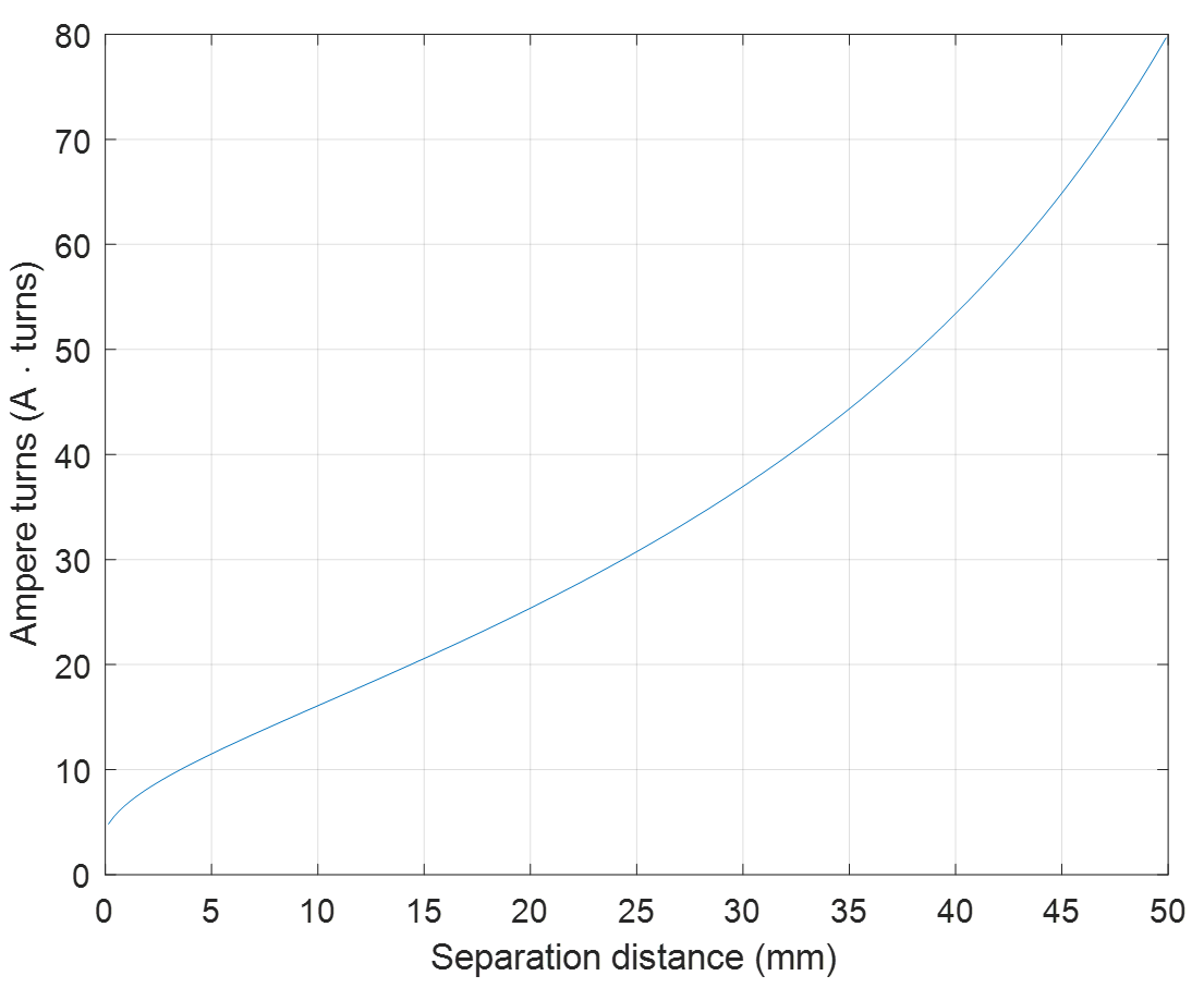
An inductively coupled system is exempt from routine NS evaluation when the product of the number of turns, n, and RMS current, IRMS (in amperes), in the transmission coil is less than or equal to the result on the right-hand side of equation (1), where x represents the separation distance in millimetres between the coil and exposed tissue.
\(nI_{RMS}≤24\left( \frac{7.827}{(x+0.2786)^{0.1557}}-3.953 \right)^{-1}\) (1)
The exemption is only valid when:
- the geometry of the transmission coil is circular or square
- the outer dimension (diameter for circular coils or edge length for square coils) of the transmission coil is less than or equal to 100 mm
- the minimum separation distance x is greater than or equal to 0.15 mm and
- the maximum separation distance x is less than or equal to 50 mm
The thickness of the enclosure is permitted to be included in the separation distance x.
This equation is based on an approximation of internal E-fields resulting from general magnetic field sources determined through computational electromagnetic simulations.
Equation (1) is plotted in figure 1. Devices with ampere-turns less than or equal to the curve are deemed exempt for the specific separation distances where this occurs. Similarly, the required separation distance for a fixed ampere-turn value corresponds to the appropriate intersection point. Note that the transmitting device might increase the current when the separation distance increases (e.g. based on feedback sent by the receiving device) as such, compliance with the exemption limit needs to be verified for all separation distances allowed in the device’s instructions of use.
Figure 1: Ampere-turns versus separation for NS exemption limits
The applicable exemption limits for the maximum allowable ampere-turns at specific separation distances are summarized in table 10.
Table 10: NS evaluation exemption limits for routine evaluation
| Separation distance (mm) |
0.15 |
5 |
10 |
15 |
20 |
25 |
30 |
35 |
40 |
45 |
50 |
|---|---|---|---|---|---|---|---|---|---|---|---|
| Maximum ampere-turns (\(A \cdot turns\)) |
4.8 |
11.4 |
16.0 |
20.5 |
25.3 |
30.7 |
36.9 |
44.3 |
53.4 |
64.8 |
80.0 |
6.2.3 Capacitive systems
Exemption limits for capacitive systems are not currently available, therefore a detailed NS evaluation as per section 7.3 shall be performed.
6.3 SAR exemption limits
Devices operating at or below the applicable output power levels (adjusted for tune-up tolerance) specified in table 11, based on the separation distance, are exempt from SAR evaluation. The separation distance, defined as the distance between the user and/or bystander and the antenna and/or radiating element of the device or the outer surface of the device, shall be less than or equal to 20 cm for these exemption limits to apply.
Table 11: Power limits for exemption from routine SAR evaluation based on the separation distance
| Frequency (MHz) | ≤ 5 mm (mW) | 10 mm
(mW) |
15 mm (mW) | 20 mm (mW) | 25 mm (mW) | 30 mm (mW) | 35 mm (mW) | 40 mm (mW) | 45 mm (mW) | > 50 mm (mW) |
|---|---|---|---|---|---|---|---|---|---|---|
| ≤ 300 |
45 |
116 |
139 |
163 |
189 |
216 |
246 |
280 |
319 |
362 |
| 450 |
32 |
71 |
87 |
104 |
124 |
147 |
175 |
208 |
248 |
296 |
| 835 |
21 |
32 |
41 |
54 |
72 |
96 |
129 |
172 |
228 |
298 |
| 1900 |
6 |
10 |
18 |
33 |
57 |
92 |
138 |
194 |
257 |
323 |
| 2450 |
3 |
7 |
16 |
32 |
56 |
89 |
128 |
170 |
209 |
245 |
| 3500 |
2 |
6 |
15 |
29 |
50 |
72 |
94 |
114 |
134 |
158 |
| 5800 |
1 |
5 |
13 |
23 |
32 |
41 |
54 |
74 |
102 |
128 |
The exemption limits in table 11 Table 11 are based on measurements and simulations of half-wave dipole antennas at separation distances of 5 mm to 50 mm from a flat phantom, which provides a SAR value of approximately 0.4 W/kg for 1 g of tissue.
For limb-worn devices where the 10 gram of tissue applies, the exemption limits for routine evaluation in table 11 are multiplied by a factor of 2.5.
For controlled-use devices where the 8 W/kg for 1 gram of tissue applies, the exemption limits for routine evaluation in table 11 Table 11 are multiplied by a factor of 5.
When the operating frequency of the device is between two frequencies located in table 11, linear interpolation shall be applied for the applicable separation distance. If the separation distance of the device is between two distances located in table 11, linear interpolation may be applied for the applicable frequency. Alternatively, the limit corresponding to the smaller distance may be employed. For example, in case of a 7 mm separation distance, either use the exception value for a 5 mm separation distance or interpolate between the limits corresponding to 5 mm and 10 mm separation distances.
For implanted medical devices, the exemption limit for routine SAR evaluation is set at an output power of 1 mW, regardless of frequency.
The SAR levels from exempted transmitters shall be included in the compliance assessment and the determination of the TER. Detailed guidance is included in sections 7.1.8 and 8.2.2.1.
6.4 Localized APD exemption limits
Devices operating at or below the applicable output power level (adjusted for tune-up tolerance) for the specified separation distances defined in table 12 are exempt from APD evaluation. The separation distance, defined as the distance between the user and/or bystander and the antenna and/or radiating element of the device, must be less than or equal to 20 cm for these exemption limits to apply.
Table 12: APD evaluation exemption limits for routine evaluation
| Freq (GHz) | ≤ 5 mm (mW) | 10 mm (mW) | 15 mm (mW) | 20 mm (mW) | 25 mm (mW) | 30 mm (mW) | 35 mm (mW) | 40 mm (mW) | 45 mm (mW) | > 50 mm (mW) |
|---|---|---|---|---|---|---|---|---|---|---|
| 7 |
3 |
13 |
26 |
40 |
57 |
82 |
117 |
161 |
201 |
240 |
| 9 |
3 |
13 |
21 |
35 |
57 |
80 |
108 |
146 |
186 |
229 |
| 20 |
3 |
9 |
15 |
24 |
36 |
49 |
65 |
85 |
106 |
131 |
| 30 |
3 |
14 |
24 |
38 |
56 |
78 |
105 |
137 |
173 |
214 |
The exemption limits in table 12 are based on simulations of half-wave dipole antennas at separation distances of 5 mm to 50 mm from a flat phantom, which provides an APD value of approximately 5 W/m2.
For controlled-use devices where the 100 W/m2 limit applies, the exemption limits for routine evaluation in table 12 are multiplied by a factor of 5.
The APD levels from exempted transmitters shall be included in compliance assessments. Detailed guidance is included in sections 7.1.9 and 8.2.2.2.
6.5 IPD exemption limit
A transmitter producing emissions in the 6GHz -30 GHz frequency range (i.e. where the occupied bandwidth (99% emission bandwidth) is fully contained within this range) is exempt from routine IPD evaluation if the output power (adjusted for tune-up tolerance) is less than or equal to 1 mW (0 dBm).
IPD from exempted transmitters shall be included in compliance assessments. Detailed guidance is included in section 8.2.2.4.
6.6 Field reference level exposure exemption limits
Field reference level (FRL) exposure evaluation is required if the separation distance between the user and/or bystander and the device’s radiating element is greater than 20 cm (i.e. mobile devices), except when the device operates as follows:
- below 20 MHz and the source-based, time-averaged maximum EIRP of the device is equal to or less than 1 W (adjusted for tune-up tolerance)
- at or above 20 MHz and below 48 MHz and the source-based, time-averaged maximum EIRP of the device is equal to or less than \(4.49/ƒ^{0.5} W\) (adjusted for tune-up tolerance), where ƒ is in MHz
- at or above 48 MHz and below 300 MHz and the source-based, time-averaged maximum EIRP of the device is equal to or less than 0.6 W (adjusted for tune-up tolerance)
- at or above 300 MHz and below 6 GHz and the source-based, time-averaged maximum EIRP of the device is equal to or less than \(1.31×10^{-2} f^{0.6834} W\) (adjusted for tune-up tolerance), where ƒ is in MHz
- at or above 6 GHz and the source-based, time-averaged maximum EIRP of the device is equal to or less than 5 W (adjusted for tune-up tolerance)
In these cases, the information contained in the RF exposure technical brief may be limited to information that demonstrates how the EIRP was derived.
7. Evaluation methods
General guidance, evaluation hierarchy, and acceptable evaluation methods for NS, SAR, APD, IPD and FRL are outlined in the following sections.
7.1 General guidance
The following sections outline various compliance evaluation methods.
7.1.1 Assessment flowchart
Assessments for NS, SAR, APD, IPD and FRL may be completed through any combination of measurements and/or simulations. The flowchart outlined in figure 2 provides a method to assess the EUT for each required assessment. Additional details on each assessment method are outlined in the following sections.
Figure 2: RF exposure assessment flowchart

7.1.2 Measurement-based methods
Measurement-based methods shall use equipment that has a valid calibration certificate for the period during, which measurements are performed. Key parameters required to verify the calibration status of each component, devices, apparatus, probes and antennas (e.g. dipole antennas) employed during measurements and target values for system validation/system checks shall be recorded in the RF exposure technical brief; this includes calibration certificates for the equipment.
Devices shall be tested while transmitting at the nominal rated output power that is defined for post production devices that will be released onto the Canadian market. Tune-up tolerances shall be added to the measured value to obtain the final reported value.
7.1.3 Simulation-based methods
Simulation-based methods include techniques that shall be validated in accordance with international standards, unless stated otherwise. The normative international standards are denoted in the relevant assessment procedure(s).
7.1.4 Test reduction methods
Test reduction methods employed to reduce the testing burden and ensure timely access to the Canadian market are accepted. However, the allowance to apply test reduction methods does not constitute an exemption from compliance with the applicable exposure limit(s) and the other relevant requirements. The use of any test reduction methods for certification purposes does not prevent ISED from employing enforcement measures regarding non-compliances with Health Canada’s Safety Code 6 limits specified in this document; including those that are outside of the scope of test reduction methods.
The specific test reduction methods for NS, SAR, APD, IPD and FRL are outlined in each specific standard.
7.1.5 Devices with multiple transmitters
Devices with multiple transmitters may be subject to evaluation by a combination of the evaluation methods specified in RSS-102, as applicable to each transmitter in the device.
In addition, all transmitters that transmit simultaneously shall be accounted for in the overall declaration of compliance of the device.
7.1.6 Time-averaged SAR (TAS) and time-averaged PD (TPD) algorithms
All new TAS algorithms require approval prior to being added to the ISED approved TAS algorithms list. ISED approval will be granted following a satisfactory review of the algorithm documentation, and, when deemed necessary, via a physical evaluation.
When submitting an inquiry to ISED regarding a new TAS algorithm, the following information is required:
- a detailed operational description of the TAS algorithm including any limitations or restrictions on its use (e.g. the TAS algorithm may be limited to use within tablets or laptops and not intended for use in smartphones or small form factor devices such as smart watches)
- integration manual, which includes a list of all parameters that are configurable for host integration
- validation criteria considerations and validation results on a representative host including detailed descriptions of the procedures and test setup used for validation
ISED may, at its discretion, request additional information for approval of a TAS algorithm.
The validation criteria shall follow the requirements herein. For implementations falling outside the scope of the normative TAS of RSS-102.SAR.MEAS, Measurement Procedure for Assessing Specific Absorption Rate (SAR) Compliance in Accordance with RSS-102 additional validation criteria shall be considered to ensure that the implementation can conservatively assess the source-based time-average power over any 6-minute reference period.
TAS algorithm approval packages shall be submitted to ISED via the following email address: certificationbureau-bureauhomologation@ised-isde.gc.ca. It is recommended that “TAS approval package” be included in the subject line of the email.
TAS algorithm approval is a lengthy process which takes several weeks and in some cases months, especially when a physical evaluation is warranted.
Applicants and other responsible parties (e.g. manufacturers, product integrators, CABs) should contact ISED as early as possible to minimize delays.
If the review of the TAS approval package is successful, the TAS algorithm will be listed on the ISED approved TAS algorithms list website and an approval letter will be provided to the applicant. Final products or modules employing the approved TAS algorithm will then be able to undergo the TAS validation procedures outlined in the normative TAS of RSS-102.SAR.MEAS and other certification requirements. The applicant shall provide the approval letter to the CB. It shall be included as part of the certification filing submitted to ISED for the product to be listed on the REL.
A similar process is to be followed for time-averaged PD (TPD) algorithms.
7.1.7 Devices employing sensors or mechanisms to set transmission power levels
This section specifies the requirements for devices employing sensors or mechanisms for controlling their transmission power level.
7.1.7.1 General requirements
RF exposure mitigation strategies employed in devices can include the use of sensors or mechanisms to determine a device operating state. The operating state is employed to select specific output power for transmissions from the device. Sensors or mechanisms used for this purpose shall be validated by the manufacturer where applicable. The implementation of the sensors or mechanisms within a final product shall be validated by an ISED-recognized test laboratory. The validations are required to be completed before a device can be declared compliant to RSS-102.
Examples of sensors or mechanisms that need to be validated include, but are not limited to, the following:
- proximity sensors
- motion sensors including, gyroscopes and accelerometers
- hall effect or gravity sensors
- voice routing (where the presence of audio is employed to determine operating state)
Requests for guidance may be submitted online through the submission of a General Inquiry for situations where ISED approved or standardized test procedures are not available.
7.1.7.2 Manufacturer validation requirements
In the RF exposure technical brief, manufacturers shall clearly indicate, which RF exposure mitigation sensors or mechanisms are integrated in their device and the corresponding validation, which shall include the following:
- the procedures employed to validate the sensor or mechanism
- applicable operating states
- the threshold(s) or limits used to establish or identify a given operating state
- details of how the specific threshold(s) was (were) established including how device uncertainties/component specifications were considered in establishing the threshold(s)
- For example, motion sensors that use accelerometers have a predefined acceleration (in m/s) that is used to distinguish between when a device is in motion and when it is resting on a table.
- details of all applicable and foreseeable use cases employed to determine thresholds and
- measurement results of the validations performed
This section (manufacturer validation requirements) applies for all sensor-type validations except for proximity sensors, which shall be validated using the procedures outlined in section 7.7 of IEC/IEEE 62209-1528.
7.1.7.3 Test laboratory validation requirements
Refer to annex C for applicable validation procedures that shall be followed. All results shall be reported in the RF exposure technical brief.
7.1.8 SAR estimation for exempted transmitters
SAR values from exempted transmitters shall be included in the total exposure assessment. A SAR value of 0.4 W/kg for 1 g, 1 W/kg for 10 g, or an estimated SAR value based on the ratio of the power level and the power exemption limit may be used to determine the standalone SAR value for test configurations that do not require a SAR evaluation based on test reductions or on the exemption limits outlined in section 6.3. The estimated SAR value, SARestimated is calculated using equation (2):
\(SAR_{estimated}=\frac{P_{max}}{P_{max,exemption}} ×0.25 ×SAR_{limit} W/kg\) (2)
where:
- \(P_{max}\) is the maximum power level including tune-up tolerance for the exempted transmitter
- \(P_{max,exemption}\) is the maximum power level of exemption at the same frequency and distance for the exempted transmitter
- \(SAR_{limit}\) is the applicable SAR limit (e.g. 1.6 W/kg for 1 g or 4 W/kg for 10 g)
For example, transmitter A has a maximum output power of 2 mW and the power exemption threshold is 3 mW at that specific frequency and distance (i.e. 2.45 GHz with a separation distance of 5 mm). The estimated SAR = (2 mW / 3 mW) * 0.4 W/kg = 0.27 W/kg.
The SAR levels from exempted transmitters shall be included in the total exposure ratio assessment. Detailed guidance is included in section 8.2.2.1.
7.1.9 APD estimation for exempted transmitters
APD values from exempted transmitters shall be included in the total exposure assessment. An APD value of 5 W/m2 or an estimated APD value based on the ratio of the power level and the power exemption limit may be employed to determine the standalone APD value for test configurations that do not require an APD evaluation based on test reductions or on the exemption limits outlined in section 6.4. The estimated APD value, APDestimated, is calculated using equation (3):
\(APD_{estimated}=\frac{P_{max}}{P_{max,exemption}} ×5.0 W/m^2\) (3)
where:
- \(P_{max}\) is the maximum power level including tune-up tolerance for the exempted transmitter
- \(P_{max,exemption}\) is the maximum power level of exemption at the same frequency and distance
For example, transmitter B has a maximum output power of 11 mW and the power exemption threshold is 14 mW at that specific frequency and distance (i.e. 30 GHz with a separation distance of 10 mm). The estimated APD = (11 mW / 14 mW) * 5.0 W/m2 = 3.9 W/m2.
The APD levels from exempted transmitters shall be included in the total exposure ratio assessment. Detailed guidance is included in section 8.2.2.2.
7.1.10 WPT devices
The following sections outline the requirements for WPT devices.
7.1.10.1 WPT clients
There are no RF exposure requirements for the WPT subassembly of WPT clients. However, the RSS-102 requirements apply to other wireless modules included in the WPT device.
7.1.10.2 WPT sources
The operating frequency of a WPT source will determine the required RF exposure assessment.
7.1.10.2.1 Exemption from routine evaluation
Type 2 WPT sources (as defined in RSS-216, Wireless Power Transfer Devices)
The WPT subassembly of Type 2 WPT sources are exempt from all of the routine RF exposure evaluations specified in RSS-102.
Type 1 and Type 3 WPT sources (as defined in RSS-216)
Provided the requirements below are met, the WPT subassembly of Type 1 and Type 3 WPT sources is exempt from routine FRL and/or SAR evaluation.
- However, this exemption does not extend to NS evaluation. NS evaluation exemption shall be on the basis of the provisions outline in 6.2.
- Wireless power transfer frequency is below 1 MHz
- Output power from each primary coil (i.e. transmitter coil in the WPT source device) is less than or equal to 5 W
- The system may consist of more than one primary coil, charging one or more clients. If more than one primary coil are present, the coil pairs may be powered on at the same time
- The WPT client device is placed in direct contact with or docked onto the WPT source
- The maximum coupling surface area of the WPT source is less than or equal to 400 cm2
- The total leakage fields from all simultaneous transmitting coils are proven to be less than 30% of the applicable limits, as set out in section 5, at 10 cm from the WPT system in all directions
- The total leakage fields shall be calculated or measured based on actual and typical WPT clients of types selected such that they provide worst-case conditions. For WPT source devices with multiple fixed wireless power transfer zones that are only capable of powering/charging one client at a time, this requirement shall be met separately for each zone.
For all types of WPT sources, it is emphasized that exemption from routine evaluation is not an exemption from compliance with the applicable exposure limit(s) and the other relevant requirements.
7.1.10.2.2 Required configuration during the assessment
RF exposure shall be evaluated with the client devices charged/powered by the source device at maximum output power. Additionally, all transmitters, including those not used for wireless power transfer, shall be active simultaneously and at maximum power.
For WPT sources designed as table top devices (e.g. wireless charging pads), the maximum allowable separation distance for any SAR-based assessment is 10 cm. Refer to RSS-102.NS.MEAS, Measurement Procedure for Assessing Nerve Stimulation (NS) Compliance in Accordance with RSS-102 for the allowable separation distance provisions for NS-based assessment.
7.1.11 Novel products/technologies
An inquiry shall be submitted to ISED for novel products / technologies in the event that published guidance, such as RSSs and/or international standards, is not applicable, available, or listed on ISED list of recognized procedures.
To minimize delay in obtaining regulatory approval, applicants and other responsible parties (e.g. CABs, product integrators) should submit a General Inquiry form to ISED as early as possible. In order for ISED to determine the applicable technical and administrative requirements, the inquiry shall include sufficient information pertaining to the technology and operation of the device such as:
- operational description
- technologies
- frequency bands
- maximum output power specifications
- intended and foreseeable use cases
- exposure conditions
- proposed method of demonstrating compliance (where possible)
7.2 Assessment hierarchy
The hierarchy of assessment methods is illustrated in figure 3. The requirements relating to each assessment method are provided in the following sections.
Figure 3: Assessment method hierarchy

The assessment method hierarchy is based on an approach that is optimized to minimize the amount of analysis required to determine compliance of a device to the exposure limits outlined in section 5. If it is permitted to assess a device against the reference levels, one may choose to perform the assessment via measurements or simulations. If compliance cannot be demonstrated against the reference levels, a subsequent analysis shall be performed against the basic restrictions to demonstrate compliance against the requirements of RSS-102.
7.3 Nerve stimulation
Devices that operate within the frequency range of 3 kHz to 10 MHz shall have an assessment against NS. Furthermore, portable devices operating between 100 kHz and 10 MHz shall also have an assessment against SAR as outlined in section 7.4.
NS compliance may be determined by measurements or simulations. All measurement-based NS evaluations shall be completed in accordance with RSS-102.NS.MEAS. All computational-based NS evaluations shall be completed in accordance with RSS-102.NS.SIM, Simulation Procedure for Assessing Nerve Stimulation (NS) Compliance in Accordance with RSS-102.
For NS, a basic restriction assessment is generally preferred, particularly when the exposure region is within the reactive near-field region of the transmitting antenna(s), which is often the case below 10 MHz.
When the practical limitations of the test equipment or tissue-equivalent phantom prevent a measurement-based assessment, a simulation (computational) assessment against the basic restrictions may be performed.
It is permissible to assess against the reference levels when an assessment against the basic restrictions is not feasible or practical. In these situations, the reference levels become levels that shall not be exceeded.
7.4 SAR
Portable devices (operated at 20 cm or less from the body) containing a radiating element operating at a frequency between 100 kHz and 6 GHz shall undergo a SAR evaluation.
SAR compliance may be assessed by measurements or by simulations. All measurement-based SAR evaluations shall be completed in accordance with RSS-102.SAR.MEAS. All computational-based SAR evaluations shall be completed in accordance with RSS-102.SAR.SIM, Simulation Procedure for Assessing Specific Absorption Rate (SAR) Compliance in Accordance with RSS-102 (currently in development).
7.5 Localized power density
Devices that have a radiating element that operate above 6 GHz and up to 300 GHz shall undergo a power density evaluation.
Portable devices operating between 6 GHz and 10 GHz shall normally be assessed in accordance with the requirements for localized APD-based analyses found in section 7.5.1. Portable devices may be assessed against the reference levels (localized IPD) when an assessment against the basic restrictions is not feasible or practical. In these situations, the reference levels become levels that shall not be exceeded.
Mobile devices should be assessed in accordance with the requirements for localized IPD-based analyses found in section 7.5.2.
7.5.1 Localized absorbed power density
Portable devices operating from 6 GHz to 7.125 GHz shall be assessed in accordance with the requirements outlined in the relevant annex of RSS-102.SAR.MEAS.
Localized APD requirements for portable devices operating above 7.125 GHz are currently not available. Meanwhile, these portable devices can be evaluated in accordance with the requirements outlined in section 7.5.2.
7.5.2 Localized incident power density
Localized IPD compliance may be determined by measurements or by simulations. All measurement-based localized IPD evaluations shall be completed in accordance with RSS-102.IPD.MEAS, Measurement Procedure for Assessing Incident Power Density (IPD) Compliance in Accordance with RSS-102. All computational-based localized IPD evaluations shall be completed in accordance with RSS-102.IPD.SIM, Simulation procedure for assessing incident power density (IPD) compliance in accordance with RSS-102.
For portable devices operating above 6 GHz, but not in the 60 GHz band, a General Inquiry form shall be submitted to ISED to describe the proposed method and how it can be employed to perform a conservative RF exposure assessment.
7.6 Field reference level (FRL) evaluation
Mobile devices or other apparatus under the scope of RSS-102 requiring an FRL exposure evaluation shall be assessed in accordance with the requirements outlined in the latest version of IEEE C95.3.
If the device is designed such that more than one antenna can transmit at the same time (i.e. simultaneous transmission), the FRL exposure evaluation shall be conducted while all antennas are transmitting. The individual exposure level ratio of each transmitting antenna shall be totalled and used for compliance purposes. Alternatively, a probe shape to the reference levels limits specified in 5.3 with a wide enough bandwidth to capture all the simultaneous transmission may be used to perform the FRL assessment without summing the individual exposure level ratio.
If the device has more than one antenna, but is not designed to have more than one antenna transmit at the same time, the FRL exposure evaluation of the device shall be performed for each of the individually transmitting antennas. The maximum FRL value shall be recorded and used for compliance purposes.
If the device combines groups of simultaneous and non-simultaneous transmitting antennas, the worst-case of the above scenarios applies.
An FRL evaluation is permitted for devices with antennas operating in the far field with separation distance of less than 20 cm; the exposure condition shall be in the far field of the antenna.
8. Total exposure
Compliance with the limits to prevent NS and thermal effects is demonstrated if the worst-case total exposure ratios (TERs) corresponding to each effect are less than or equal to 1. These TERs are evaluated separately, based on the corresponding NS- or thermal-based exposure ratios and in accordance with the following sections.
8.1 NS-based total exposure ratio (3 kHz to 10 MHz)
The frequency range associated with the NS-based limits are outlined in sections 5.2.1 and 5.3.1. As a result, the NS-based TER, denoted by TERNS can be evaluated based on the NS-based exposure ratios obtained in RSS-102.NS.MEAS and/or RSS-102.NS.SIM in equation (4).
\(TER_{NS}=∑_{n=1}^N ER_{NS-BR,n}+max\left[ ∑_{m=1}^M ER_{NS-ERL,m},∑_{m=1}^M ER_{NS-HRL,m} \right]\) (4)
where:
- N is the number of simultaneously operating transmitters for which an assessment against the basic restriction for internal E-field has been performed
- \(ER_{NS-BR,n}\) is the NS-based exposure ratio of the n-th simultaneously operating transmitter for which an assessment against the basic restriction for internal E-field has been performed
- M is the number of simultaneously operating transmitters for which an assessment against the NS-based reference levels has been performed
- \(ER_{NS-ERL,m}\) is the NS-based exposure ratio of the m-th simultaneously operating transmitter for which an assessment against the NS-based reference level for incident E-field has been performed and
- \(ER_{NS-HRL,m}\) is the NS-based exposure ratio of the m-th simultaneously operating transmitter for which an assessment against the NS-based reference level for incident H-field has been performed
The maximum \(TER_{NS}\) values shall be provided in the RF exposure technical brief for each exposure condition, and the highest value shall be clearly indicated. Compliance with NS-based limits is demonstrated if the worst-case TER_NS≤1.
Situations where the \(TER_{NS} \gt 1\) shall be reported to ISED via a General Inquiry form. Alternative methods considering point-by-point evaluations may be considered on a case-by-case basis.
8.2 Thermal-based total exposure ratio
The thermal-based exposure ratio is divided into two key components:
- the thermal-based ER at and below 10 MHz, denoted \(ER_{therm \le 10 MHz}\)
- the thermal-based ER above 10 MHz, denoted \(ER_{therm \gt 10 MHz}\)
The following sections outline these two components.
To evaluate the TER, the NS-based exposure ratio shall not be added to the thermal-based exposure ratios. Each shall be assessed separately.
8.2.1 Thermal-based ER below 10 MHz
The exposure ratio \(ER_{EH-SAR}\) for transmitters operating between 100 kHz and 10 MHz for which compliance was determined against the SAR-based reference levels for the incident E- and/or H-fields is shown in equation (5).
\( ER_{EH-SAR,a}=\Bigg\{ \begin{matrix} \left(\frac{H_{SAR,a}}{H_{RL-SAR,a}}\right)^2, & 100kHz \le f_a \lt f_{env} \\ \max \left[ \left(\frac{E_{SAR,a}}{E_{RL-SAR,a}}\right)^2,\left(\frac{H_{SAR,a}}{H_{RL-SAR,a}}\right)^2 \right], & f_{env} \le f_a \lt 10MHz \end{matrix}\) (5)
where:
- HSAR,a is the RMS of the incident H-field from the a-th transmitter, time-averaged in accordance with a SAR-based assessment
- HRL-SAR,a is the SAR-based reference level for the incident H-field, which is applicable to the a-th transmitter
- ESAR,a is the RMS of the incident E-field from the a-th transmitter, time-averaged in accordance with a SAR-based assessment
- ERL-SAR,a is the SAR-based reference level for the incident E-field that is applicable to the a-th transmitter
- fa is the operating frequency of the a-th transmitter and
- fenv is 1.10 MHz when considering the limits for uncontrolled environments and 1.29 MHz when considering the limits for controlled environments, in accordance with Health Canada’s Safety Code 6
The exposure ratio resulting from SAR-based assessments on the basic restriction ( \(ER_{SAR-BR}\) ) for transmitters operating at or below 10 MHz is shown in equation (6).
\(ER_{SAR-BR,b}=\frac{SAR_b }{SAR_{limit-BR}}\) (6)
where:
- SARb is the SAR value for the b-th transmitter/test frequency and
- SARlimit-BR is the basic restriction limit that is applicable to the b-th transmitter/test frequency.
The exposure ratio resulting from a SAR assessments based on the reference level (\(ER_{SAR-RL}\)) for transmitters operating at or below 10 MHz is shown in equation (7).
\(ER_{SAR-RL,c}=\frac{SAR_{c}}{SAR_{limit-RL}}\) (7)
where:
- \(SAR_c\) is the SAR value for the c-th transmitter/test frequency and
- \(SAR_{limit-RL}\) is the reference level that is applicable to the c-th transmitter/test frequency
The ER associated with the thermal-based ER below 10 MHz, (\(ER_{therm \le 10MHz}\)) is shown in equation (8).
\(ER_{therm≤10 MHz}=∑_{a=1}^A ER_{EH-SAR,a}+∑_{b=1}^B ER_{SAR-BR,b} +∑_{c=1}^C ER_{SAR-RL,c}\) (8)
where:
- A is the total number of transmitters for which an assessment against the SAR-based reference levels for the incident E- and H-fields has been performed
- \(ER_{EH-SAR,a}\) is the exposure ratio contribution from the a-th transmitter for which an assessment against the SAR-based reference levels for the E- and H-fields has been performed as shown in equation (5)
- B is the number of simultaneously operating transmitters for which an assessment against the basic restriction for SAR may have been performed
- \(ER_{SAR-BR,b}\) is the SAR-based exposure ratio of the b-th simultaneously operating transmitter for which an assessment against the basic restriction for SAR may have been performed as shown in equation (6)
- C is the number of simultaneously operating transmitters for which an assessment against the SAR-based reference levels may have been performed and
- \(ER_{SAR-RL,c}\) is the SAR-based exposure ratio of the c-th simultaneously operating transmitter for which an assessment against the SAR-based reference levels may have been performed as shown in equation (7)
8.2.2 Thermal-based ER above 10 MHz
Thermal-based ER for transmitters above 10 MHz can be calculated using SAR-, APD-, and IPD-based measurements/simulation results as outlined in sections 8.2.2.1, 8.2.2.2 and 8.2.2.3, respectively. The exposure from exempted transmitters shall be included in the determination of the thermal-based ER above 10 MHz.
8.2.2.1 SAR-based ER (above 10 MHz to 6 GHz)
The thermal-based ER for transmitters operating above 10 MHz ( \(Er_{therm \gt 10MHz}\) ) is evaluated based on the operating frequency or test frequency and the type of measurement or simulation result. The ER resulting from SAR-based measurements/simulations above 10 MHz to 6 GHz can be calculated using equation (9)
\(ER_{therm>10\ MHz,t}=\frac{SAR_t }{SAR_{limit,t}},10\ MHz \lt f_t \le 6\ GHz\) (9)
where:
- \(SAR_t\) is the SAR value of the t-th transmitter/test frequency
- \(SAR_{limit,t}\) is the basic restriction limit that is applicable for the t-th transmitter and
- \(f_t\) is the operating frequency / test frequency of the t-th transmitter
The ER resulting from SAR-based exempted transmitters can be calculated using equation (10) :
|
\(ER_{therm \gt 10\ MHz,u}=\frac{SAR_{estimated,u} }{SAR_{limit,u}} ,10\ MHz \lt f_u \le 6\ GHz\) |
(10) |
where:
- SARestimated,u is the SAR value of the exempted u-th transmitter/test frequency (refer to section 7.1.8)
- SARlimit,u is the basic restriction limit that is applicable for the u-th transmitter and
- fu is the operating frequency / test frequency of the u-th transmitter
8.2.2.2 APD-based ER (above 6 GHz to 10 GHz)
ER from APD-based measurements above 6 GHz to 10 GHz can be calculated using equation (11) :
|
\(ER_{therm>10\ MHz,v}=\frac{APD_v }{APD_{limit,v}},6\ GHz \lt f_v ≤ 10\ GHz\) |
(11) |
where:
- APDv is the APD value for the v-th transmitter/test frequency
- APDlimit,v is the basic restriction limit that is applicable for the v-th transmitter and
- fv is the operating frequency / test frequency of the v-th transmitter
The ER resulting from APD-based exempted transmitters can be calculated using equation (12) :
|
\(ER_{therm \gt 10\ MHz,w}=\frac{APD_{estimated,w}}{APD_{limit,w}}, 6\ GHz \lt f_w \le 30\ GHz\) |
(12) |
where:
- \(APD_{estimated,w}\) is the APD value of the exempted w-th transmitter/test frequency (refer to section 7.1.9)
- \(APD_{limit,w}\) is the basic restriction limit that is applicable for the w-th transmitter and
- \(f_w\) is the operating frequency/test frequency of the w-th transmitter
8.2.2.3 IPD-based ER (above 6 GHz to 300 GHz)
IPD-based measurements above 6 GHz to 30 GHz can be calculated using equation (13):
\(ER_{therm \gt 10\ MHz,x}=\frac{psPD_x }{psPD_{limit,x}},6\ GHz \lt f_x \le 30\ GHz\) (13)
where:
- psPDx is the peak spatial-average power density value for the x-th transmitter
- psPDlimit,x is the applicable peak spatial-average power density reference level limit for the x-th transmitter and
- fx is the operating frequency / test frequency the x-th transmitter
PD-based measurements above 30 GHz to 300 GHz can be calculated using equation (14):
\(ER_{therm \gt 10\ MHz,y}=max \left[ \frac{psPD_y }{psPD_{limit,y}} ,\frac{pPD_y }{pPD_{limit,y}} \right],30\ GHz \lt f_y \le 300\ GHz\) (14)
where:
- psPDy is the peak spatial-average power density value for the y-th transmitter
- psPDlimit,y is the applicable peak spatial-average power density reference level limit for the y-th transmitter
- pPDy is the spatial peak power density value for the y-th transmitter
- pPDlimit,y is the applicable spatial peak power density reference level limit for the y-th transmitter and
- fy is the operating frequency/test frequency the y-th transmitter
8.2.2.4 Devices producing emissions in the 6 GHz to 30 GHz range under the 1 mW exemption
The ER for a transmitter producing emissions in the 6 GHz to 30 GHz frequency range and is exempted in accordance with section 6.5 (i.e. where the occupied bandwidth (99% emission bandwidth) and is fully contained within this range) shall be accounted for by using equation (15):
\(ER_{exempted_{1mW^{,z}}} = 0.1 \left( \frac{max \left[ P_{cond,z} , P_{EIRP,z} \right] }{1\ mW} \right)\) (15)
where:
- \(ER_{exempted_{1\ mW^{,z}}}\) is the exposure ratio associated with the z-th exempted transmitter
- Pcond,z is the maximum source based, time-averaged conducted power produced by the the z-th exempted transmitter (mW) (i.e. delivered to a perfectly matched, load/antenna, adjusted for tune-up tolerance) and
- PEIRP,z is the maximum source based, time-averaged EIRP produced by the the z-th exempted transmitter (mW), adjusted for tune-up tolerance
The exposure ratio contribution from exempted transmitters \(ER_{exempted_{1mW^{,z}}}\) shall be included in the TER evaluation for all device surfaces and edges that are within 25 mm of the associated antenna.
8.2.3 TER
The various \(ER_{therm \le 10 MHz}\) and \(ER_{therm \lt 10 MHz}\) from each of the different transmitters and different exposure metrics can be combined to determine the TER for all transmitters (TERtherm) using equation (16):
(16)
where:
- T is the number of simultaneously operating transmitters for which an assessment against the basic restriction for SAR may have been performed (refer to section 8.2.2.1)
- U is the number of simultaneously operating exempted transmitters for which an estimate against the basic restriction for SAR may have been performed (refer to section 8.2.2.1)
- V is the number of simultaneously operating transmitters for which an assessment against the basic restriction for APD may have been performed (refer to section 8.2.2.2)
- W is the number of simultaneously operating exempted transmitters for which an estimate against the basic restriction for APD may have been performed (refer to section 8.2.2.2)
- X is the number of simultaneously operating transmitters (operating between 6 GHz and 30 GHz) for which an assessment against the IPD level may have been performed (refer to section 8.2.2.3)
- Y is the number of simultaneously operating transmitters (operating between 30 GHz and 300 GHz) for which an assessment against the IPD level may have been performed (refer to section 8.2.2.3) and
- Z is the number of simultaneously operating transmitters for which the 1 mW exemption as outlined in section 6.5 applies (refer to section 8.2.2.4)
Only contributions from unique transmitters shall be included in the calculation of the \(TER_{therm}\). For instance, both APD and psPD evaluations in the 6 GHz to 10 GHz frequency range for the same transmitter should not be summed; the maximum ER is to be employed in this instance.
Compliance with the SAR-PD-based RF exposure limits is achieved if \(TER_{therm} ≤ 1\). Refer to section 8.2.4 if \(TER_{therm} > 1\) and if the device contains multiple antennas or multiple transmitters.
8.2.4 Devices with multiple antennas or multiple transmitters
The determination of \(TER_{therm \gt 10 MHz}\) in section 8.2.3 assumes that all transmitters are simultaneously transmitting from the same location. However, ISED accepts the FCC’s SAR to peak location separation ratio (SPLSR) method to determine test reduction for simultaneous transmission when \(TER_{therm } > 1\) for SAR and APD applications (below 10 GHz). The SPLSR is calculated in accordance with equation (17):
where:
- SAR1 and SAR2 are the SAR value for the 1st and 2nd transmitter, respectively
- SARlimit is the applicable basic restriction limit
- APD1 and APD2 is the APD value for the 1st and 2nd transmitter, respectively
- APDlimit is the applicable basic restriction limit and
- Distance is the separation distance between the peak exposure location of the 1st and 2nd transmitter in mm
Note: Simultaneously transmitting antenna combinations must be considered one pair at a time to determine SPLSR for test reduction consideration.
Simultaneous transmission testing may be exempted when the transmitters are considered to be spatially separated as follows:
- SPLSR ≤ 0.02 for head, neck and trunk exposure conditions
- SPLSR ≤ 0.013 for limb exposure conditions
To apply SPLSR, the separation distance and configuration for each individual transmitter shall be the same. This may imply conducting additional SAR measurements on test conditions that are normally exempted through test reduction.
All other situations where the TER exceeds unity shall be reported to ISED. Alternative methods considering point-by-point evaluations may be considered on a case-by-case basis. The TER shall be documented in the RF exposure technical brief.
Annex A: RF exposure technical brief cover sheet
This annex contains information that shall be included in the RF exposure technical brief cover sheet, which may be updated from time to time.
A.1 RF exposure technical brief cover sheet
The worst-case values of SAR, APD and IPD shall be reported in the sections below.
Must report values or enter the following codes: N/A for not applicable, N/P for not performed or N/V for not available. Download the equivalent PDF here.
Applicant/Product Information
Company Number:
ISED Certification #:
PMN:
HMN:
HVIN:
FVIN:
Applicant:
Exposure Limits Used: \(\Box \) General Public Use \(\Box \) Controlled Use
Multiple Transmitters: \(\Box \) Yes \(\Box \) No
SAR Test Lab: __________________
SAR: Head exposure condition
Duty Cycle: _____ %
Compliance Dist.: ________ mm
SAR Value: __________________W/kg \(\Box \) Measured \(\Box \) Simulated
SAR: Body exposure condition
Duty Cycle: _____ %
Compliance Dist.: _______ mm
SAR Value: __________________W/kg \(\Box \) Measured \(\Box \) Simulated
SAR: Limb exposure condition
Duty Cycle: _____ %
Compliance Dist.: _______ mm
SAR Value: __________________W/kg \(\Box \) Measured \(\Box \) Simulated
APD Test Lab: __________________
APD: Head exposure condition
Duty Cycle: _____ %
Compliance Dist.: ________ mm
APD Value: __________________W/m2 \(\Box \) Measured \(\Box \) Simulated
pAPD Value: __________________W/m2 \(\Box \) Measured \(\Box \) Simulated
APD: Body exposure condition
Duty Cycle: _____ %
Compliance Dist.: _______ mm
APD Value: __________________ W/m2 \(\Box \) Measured \(\Box \) Simulated
pAPD Value: __________________W/m2 \(\Box \) Measured \(\Box \) Simulated
APD: Limb exposure condition
Duty Cycle: _____ %
Compliance Dist.: _______ mm
APD Value: __________________ W/m2 \(\Box \) Measured \(\Box \) Simulated
pAPD Value: __________________W/m2 \(\Box \) Measured \(\Box \) Simulated
IPD Test Lab: __________________
IPD: Head exposure condition
Duty Cycle: _____ %
Compliance Dist.: ________ mm
IPD Value: _________________ W/m2 \(\Box \) Measured \(\Box \) Simulated
pIPD Value: _________________ W/m2 \(\Box \) Measured \(\Box \) Simulated
IPD: Body exposure condition
Duty Cycle: _____ %
Compliance Dist.: _______ mm
IPD Value: _________________ W/m2 \(\Box \) Measured \(\Box \) Simulated
pIPD Value: _________________ W/m2 \(\Box \) Measured \(\Box \) Simulated
IPD: Limb exposure condition
Duty Cycle: _____ %
Compliance Dist.: _______ mm
IPD Value: _________________ W/m2 \(\Box \) Measured \(\Box \) Simulated
pIPD Value: _________________ W/m2 \(\Box \) Measured \(\Box \) Simulated
Declaration of Compliance
ATTESTATION: I attest that, Annex A and the Technical Brief information was prepared by me and is correct; that the device evaluation was performed or supervised by me; that applicable measurement and evaluation methodologies have been followed; and that the device meets the SAR, APD and/or IPD limits of RSS-102.
Signature:
Date:
Name:
Title:
Annex B: Declaration of RF exposure compliance for exemption from routine evaluation limits
This annex contains information that shall be provided in the Declaration of RF exposure compliance for exemption from routine evaluation limits, which may be updated from time to time. This is to be provided when the equipment under test (EUT) meets the exemption limits for the routine evaluation in section 6 of this standard.
|
ATTESTATION: I attest that the radiocommunication apparatus meets the exemption from the routine evaluation limits in Section 6 of this standard; that the Technical Brief was prepared and the information contained therein is correct, that the device evaluation was performed or supervised by the undersigned, that applicable measurement methods and evaluation methodologies have been followed and that the device meets the SAR, NS, APD and/or FRL exposure limits of RSS-102. |
|||||||
|
Signature |
: |
||||||
|
Date |
: |
||||||
|
Name |
: |
||||||
|
Title |
: |
||||||
|
Company |
: |
||||||
|
Product Marketing Name (PMN) |
: |
||||||
|
Hardware version identification no. (HVIN) |
: |
||||||
|
Firmware version identification no. (FVIN) |
: |
||||||
|
Host marketing name (HMN) |
: |
||||||
|
ISED Certification Number |
: |
||||||
|
Applicable Exemption Limits |
|
||||||
Annex C: Sensor validation
The following procedures shall be employed for the validation of sensors and/or mechanisms employed for power reduction.
C.1 Proximity sensors
The validation procedures for proximity sensors that shall be followed are outlined in section 7.7 of IEC/IEEE 62209-1528.
C.2 Motion sensors (including, but not limited to, gyroscopes and accelerometers)
For motion sensors, an inquiry shall be submitted for detailed guidance. Guidance will be based on the draft motion sensor procedures currently being developed in the context of IEC/IEEE 62209-1528.
Upon publication of a revised IEC/IEEE 62209-1528 including the motion sensor procedure, Innovation, Science and Economic Development Canada (ISED) recognized testing laboratories will be able to perform that procedure for device certification in the Canadian market without needing to submit an inquiry to ISED.
C.3 Hall effect or gravity sensors
The following procedure shall be applied for convertible laptops that use Hall effect or gravity sensors to detect lid angle for the purpose of power reduction.
- With the lid in closed mode (0 degrees), open the screen in 10 degree increments until a mode transition occurs
- Lower the screen in 5 degree increments until the previous mode is reobtained.
- Open the screen in 1 degree increments until the mode transition from step 1 is reobtained.
- Record the output power measurement and the operating mode.
- Continue opening the screen in 10 degree increments until the next mode transition occurs.
- Repeat steps 2-5 until all mode transitions have been obtained and evaluated.
- Reverse this procedure going from tablet mode back to closed mode through all identified modes.
This procedure can be adapted to cover other devices that implement Hall effect or gravity sensors such as folding phones.
C.4 Voice routing (where the presence of audio is employed to determine operating state)
The following procedure shall be employed to verify the differences in device output power during different operating modes. The same technology shall be employed for all of the following steps. Only a single technology/band is required to be tested.
- Configure the device to be in a call such that voice is routed to the earpiece (e.g. WCDMA AMR voice call).
- Record the output power and ensure that it is within the specific tune-up tolerance for this operating mode.
- Repeat steps 1–2 for any additional configurations involving voice routing to other speakers such as the speakerphone or headsets.
Annex D: Nerve stimulation (NS) exemption limits examples (informative)
This annex contains two NS exemption limits examples.
D.1 Example 1
Consider an inductive wireless power transfer (WPT) system with a planar 10-turn spiral geometry with a maximum outer diameter of 90 mm and driven with a maximum root mean square (RMS) current of 1.0 A. The coil geometry is shown in figure D1. The coil is completely enclosed within an enclosure such that the separation distance between the coil and the nearest outer surface of the enclosure is 5 mm, as shown in figure D2.
Figure D1 : Example 1 of planar 10-turn spiral inductive WPT coil with an outer diameter of 90 mm

Figure D2: Example 1 of planar 10-turn spiral inductive WPT coil with an outer diameter of 90 mm (side view, through the enclosure)

The product of current and number of turns for this example device is 10 ampere-turns. The minimum separation is 5 mm. The maximum ampere-turns permitted for a separation distance of 5 mm is 11.4 ampere-turns. Consequently, the coil and geometry outlined in this example is exempt since the maximum ampere-turns for the example is less than the exemption limit for the specified separation distance.
D.2 Example 2
Consider an inductive WPT system with a planar 25-turn spiral geometry with a maximum outer diameter of 60 mm and driven with a maximum RMS current of 0.5 A. The coil geometry is shown in Figure D3. The coil is completely enclosed within an enclosure such that the separation distance between the coil and the nearest outer surface of the enclosure is 2 mm, as shown in Figure D4.
Figure D3: Example 2 of planar 25-turn spiral inductive WPT coil with an outer diameter of 60 mm

Figure D4: Example 2 of planar 25-turn spiral inductive WPT coil with an outer diameter of 60 mm (side view, through the enclosure)

The product of current and number of turns for this example device is 12.5 ampere-turns. The minimum separation is 2 mm. The maximum ampere-turns permitted for a separation distance of 2 mm is not included in table 10 and difficult to determine from figure 1; therefore equation (1) must be employed to determine if this application is exempt. The right-hand side of equation (1) calculated to be 8.2; the product of ampere-turns in this example is greater than the calculated term on the right-hand side of equation (1). Consequently, this application is not exempt and a detailed NS evaluation is required to be completed in accordance with RSS-102.NS.MEAS or RSS-102.NS.SIM.